Hey, It’s September already… time to start over to publish new posts about FEA :)
As you know, FEA for All is a blog for everyone, from beginners to advanced FEA experts.
Today, I decided to tackle a very basic topic (but essential to know): the shell element orientation!
What is shell elements orientation?
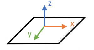
Shell elements have an orientation similar to beam elements: the X and Y axes are oriented in the plane of the shell and the Z axis is normal to it

Why is shell elements orientation important?
Element normals defines:
- The direction to apply a pressure load in a 2-D element
- Composite layup orientation
- Material property orientation
- Shell contact
- and more…
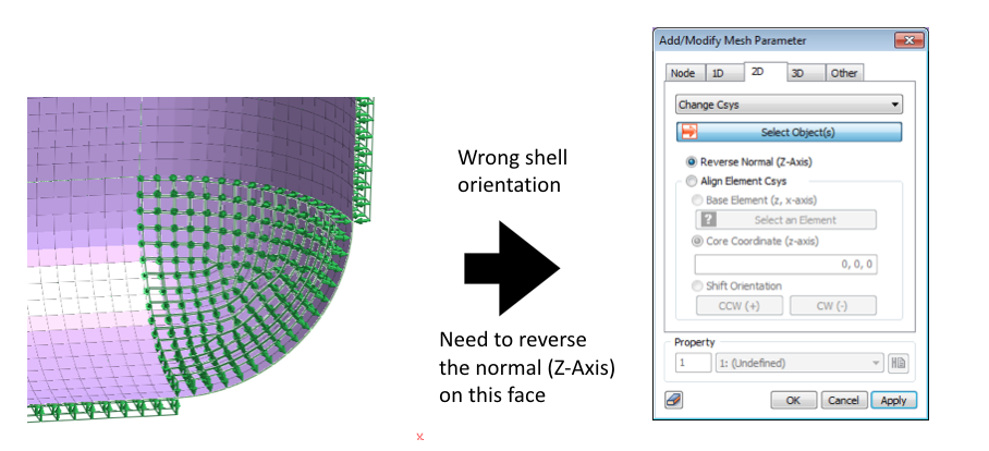
Here is a short video in which I show you the impact of the shell elements orientation on your model and how to correct your model.
What should I remember?
Always display the shell elements orientation in your shell model to check if the orientation of the normal is correct.

Applying a pressure to the mesh set is a great way to spot quickly the shell orientation problems!

That’s all for today…
There’s much more to write about, but let’s keep that for the next post ;-)
If you like this kind of short post about some important “FEA Tips”, let me know in the comments!
I read and answer to every comment :)
–Cyprien

It’s a useful tips to remember, thanks!
Hi Cyprien,
Very nice tip. I have one question related to shell element in midas. How do you specify the contact between two surfaces?
Thanks!
Contact between 2 surfaces can be done simply with an auto or manual contact… It’s in the static tab on the left if I remember well.
Hi Cyprien,
Thanks for your answer. I`m new at midas and It´s giving mi a really hard time to set the contact between two simple plates. I could identify the commands but the thing is the program (solver) do not recognize the contact.
Any tip would be greatly appreciated!
Best regards,
Ezequiel
That’s strange… are your plates by any chance perpendicular one to another? If you have contact on only an edge, you have to create a manual contact and assign it to the mesh element not to the geometry, otherwise it won’t work. Also if you have a gap in between the plates, you have to create a contact parameter and enter the distance of the gap. And finally, if it’s neither, be sure that you assigned the contact to the edges of the surface and not to the construction edges that you may have used to create the surface (that’s a common mistake)
Hi Cypries,
Thanks again for your reply. I´m just doing a simple calculation. I have two solid blocks with dimensions 20x20x5 mm. Both are in contact. Then, using solidworks I created the for each block the mid surface. After that I have imported the two surfaces into midas.
The surfaces are paralel to each other and the separation between them is 5 mm. The top surface has applied uniform pressure and the bottom the constraints ux=uy=uz=0
So, it is just the simple case of top block doing pressure over the bottom block.
The problem is that the contact is not working. The problem is solved but there is no interaction between them. There is no load transfer..
Ezequiel
OK, so you are in the case of a big gap in between that I mentioned. You have to created and associate manually a contact parameter and increase the value of the distance and set it as 5mm. Then the contact should work.
once upon in my worktime in the industry, I had some discussions about the use of shell elements enclosing thin solids of six dofs (the thickness limited by sim) and other cases reinforcing beams in shells.(ansys)
the experts speak much but not justification of some err.
results ok. (ge experiences)
regards
Hello Cyprien,
Nice post!
I have a question:
What’s the advantage of using shell elements over solid elements, other than reduced number of element required to properly resolve a thin geometry? In what situation we can/cannot use shell elements? What are the factors that decide whether using shells is a good choice or a bad choice? Are there any specific stress components that shell can model and solids cannot,i.e. plane stress/plane strain, in-plane bending stresses etc.?
If I am given a problem, is there any checklist which i can use to decide which element type would be a good choice and why?
Could you please provide some examples with your answer? Thank you very much in advance.
Regards,
Izaz
Hi Izaz, I am answering most of those questions in another article here: Why do FEA engineers use 1D,2D and 3D elements. How it will help you to understand better!
Do the normal direction and pressure direction should oppose each other.??
This depends on you and your model ;-)
If the normal direction is outward and your pressure is pushing the model, then yes directions will be opposed (and you have to specify a minus sign when you define your pressure)
You could include what if we don’t check shell normals and carry out analysis?
for ex , what if there are different shell normal in same component?
Can you tell me what is the shell thickness considered by the program?
Depends on the software and the algorithm used to calculate the thickness. I suppose it’s considered as some kind of constant offset value associated to each shell element as a property which is used to simulate the thickness that 2D elements do not have…