In this article and videos, I will teach you how to build very simple scripts using OnScale Analyst language called Symbol.
This is an opportunity to start from scratch and learn the basic commands.
I will make a Series of those videos which will be released as soon as I finish to make them.
What you will learn in this video:
- What is OnScale Analyst Mode
- The Simulation Process
- The simulation Process in OnScale with the cloud
- Designer VS Analyst Mode
- The structure of an OnScale Analyst script
- Going from Designer to Analyst
What is Onscale?
OnScale is a CAE Software using FEA and explicit nonlinear time domain methods (mainly) to calculate Multiphysic models. OnScale is mainly known for its capabilities to calculate coupled Electro-Mechanical-Acoustic models and thus used a lot for sensors, RF Filters and biomedical equipment. Nevertheless, the code is generic and include wide capabilities (Static, Thermal, Electromagnetic,…)
The Simulation Process
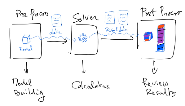
The simulation process in OnScale works the same way than any CAE software:
- Model is created in the pre-processor
- Data is then sent to the Solver (Local or on the Cloud) to be calculated
- Post-processor is used to review the results
Designer, Analyst Modes and Symbol Language
OnScale has 2 modes: Designer and Analyst
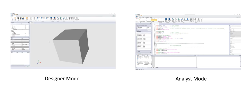
- Designer is a simpler mode in which the model can be built graphically within the Designer Mode GUI (Tutorials for Designer are available here)
- The Analyst mode is more advanced, but it uses a script language called Symbol to build the model (Check basic Symbol Evaluation rules here)
The engineers who developed that language 30+ years ago needed to have a script language, but there was none at the time! So they decided to develop this “Symbol” Language which is based on FORTRAN.
OnScale’s Simulation Process and Data Files
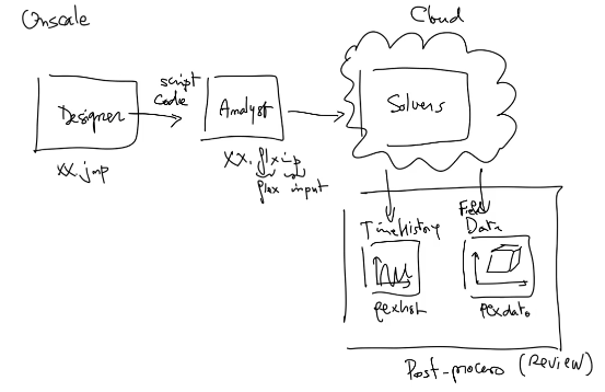
To understand how Simulation work in OnScale, you need to understand the different file formats and how the data “flows” toward the end results.
- A Model generate in the Designer Mode creates a XX.jfp File. This file contains all the data that have been graphically defined in Designer.
- OnScale reads this XX.jfp format and generate a XX.flxinp file which is a file containing script code written in Symbol language.
- This XX.flxinp script file and all the other files going with it are then sent to the solvers which are either local (on your computer) or on the cloud.
- Model is computed by OnScale Solvers and data files are produced.
- There are 2 main extensions for data files XX.flxhst and XX.flxdato
- XX.flxhst contains Time History Curves data
- XX.flxdato contains all other type of data (Pressure Field Data for example)

For example, Time history curves of Acoustic pressure for this piezoelectric transducer simulation displayed on the left would be saved into XX.flxhst, while Acoustic Pressure 3D Field Data on the right would be saved in XX.flxdato.
The structure of an OnScale Model
Now that I talked about the the simulation process, let’s talk about the structure of an OnScale Model.
An OnScale Model is like any other FEA based model, it is composed of 5 main “Building Blocks”:
- The model Geometry
- The Material Data
- The Loads
- The Boundary Conditions
- The Mesh
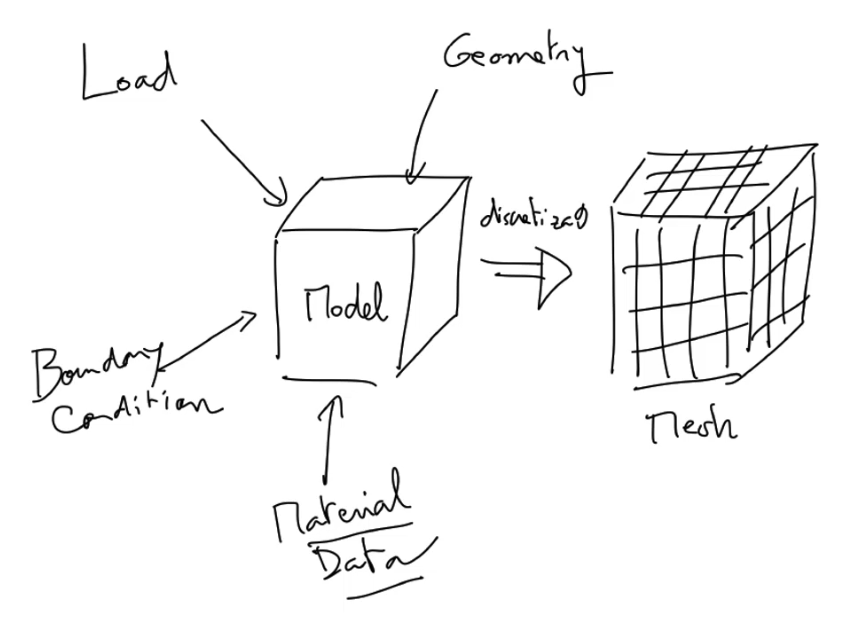
We must then Add to that:
- The Analysis settings (Simulation time,…)
- The definition of the output results (Acoustic Pressure, Displacements, Stress…)
- Any Additional and optional post-process (Time to Frequency Conversion of results using FFT, Impedance calculation, etc…)
OnScale’s Basic Analyst Commands
As we are talking about Analyst scripting here, first, we need to understand the basic commands needed to create a model.
Those commands are grid, geom, matr, site, func, boun, plod, piez, pout, data, prcs, exec
The picture below resumes which command belongs to which operation:
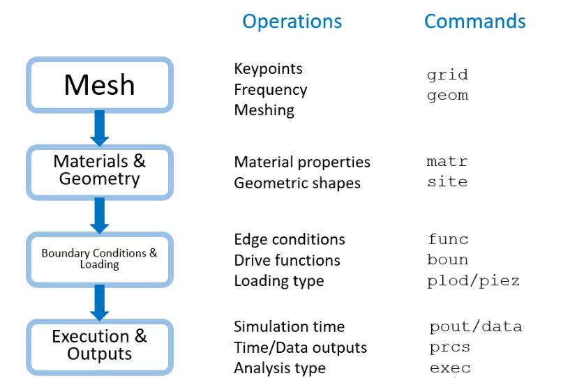
I wrote another post on the blog in which I dive deeper on each of those commands: The 10 most useful commands you need to know about in Onscale Analyst Mode
Each of the steps of the simulation process when you define a model in OnScale Designer basically corresponds to a certain number of script commands.
If you know how those commands work, you’ll understand how to generate an OnScale Analyst Model.

If you don’t get all of that at once, don’t worry, the principle of this series is to teach you about each of those commands in the most simple possible way!
In fact, I will start by showing you how to create a simple 2D Grid Model.
Creating a 2D Grid Model in OnScale Analyst Script
What you will learn in this video:
- How to generate a simple 20*20 simple 2D grid
- How to select a specific area of this grid
- How to assign material
- How to use the basic commands: geom, grid, matr, grph and term
Watch all the videos from this series in this Youtube Playlist:
Do you like this kind of Article?
Let me know what you think!
Post a comment, share the article, don’t hesitate to ask.

Great Engineering Minds are born because of relentless curiosity ;-)
Leave a Reply