The plate with a hole ! Who didn’t start to learn FEA by this simple example ?
I remember when i modeled for the first time this plate on the first NASTRAN in DOS during my FEM course, what a memorable moment… i had to run the program like a hundred times before getting a correct model… thanks to modern GUI, we can now focus on the real problem which is not the modelling, but the understand of how to get the accurate theoretical results and which parameters are important for that.
Meshes are the base of Finite Element Analysis and i will demonstrate you why !
First the problem formulation:
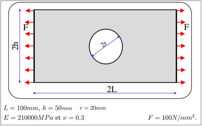
So, as the title indicate, this is a simple plate of dimensions L=100 mm x h = 50 mm made with steel with a hole of radius r = 20 mm in the middle.
As we will perform a simple linear static analysis, only 2 coefficients are required to define the material properties, the Young’s Modulus E = 210000 MPa and the poisson’s ration ν = 0.3.
a pressure load F = 100N/mm2 is applied on the 2 sides of the plate.
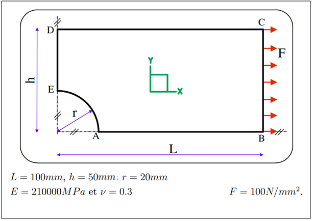
The first thing to do is to change and adapt the problem for FEA analysis:
Why do I have to formulate again the problem for FEA ?
– if you look at the previous problem, you will notice that there is no boundary condition, so the plate isn’t fixed in space. it introduce a degree of freedom that is not wanted in FEA Analysis and will complicate everything.
– When possible, symmetries should always be considered in the model in order to reduce the number of elements in the analysis. Moreover, these symmetry conditions will play the role of boundary conditions in this analysis.
In FEA analysis, the number of mesh elements and mesh element size is very important because accuracy of the results depend on it.
Even if you can calculate very complex problems of mechanics with FEA which are approaching real world models, FEA is still a numerical approximation method. So more elements you have, the smaller they are and more the results will be accurate.
here is the simple analysis process to solve this problem:
1. Create Material with properties defined above ( E = 210000 MPa and ν = 0.3 )
2. Create a 2D property of plate (Thickness = 1 mm)
3. Create the plate model using geometrical tools.
4. Mesh the plate with finite elements (choice of element size, element order and element type is critical)
5. Assign the symmetry boundary conditions to the 2 symmetrical edges of the plate.
6. Assign the Pressure load of 100N/mm2 to the right edge of the plate
7. Create a linear static analysis case
8. Launch the Analysis
9. Use the post process tools to obtain the displacement and von mises stress results
Here is a video tutorial to explain the process with more details:
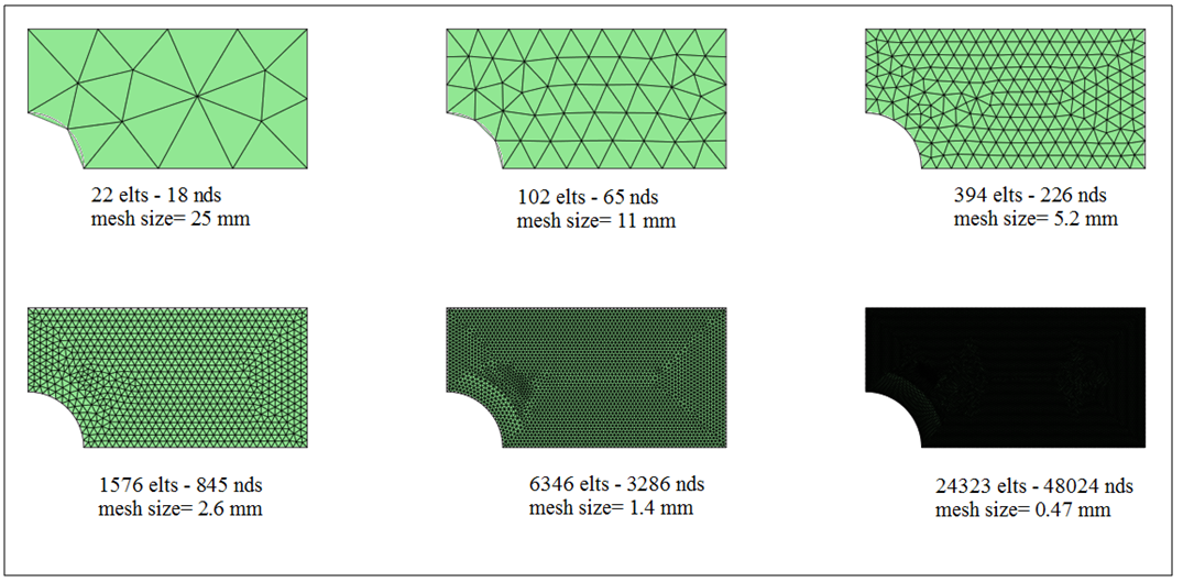
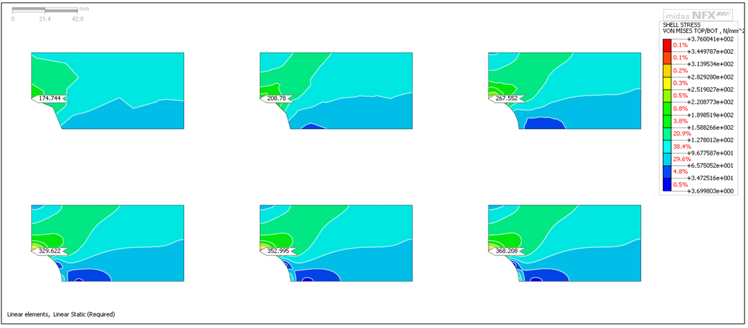
In order to see the influence of the Mesh size, it is interesting to create several models of the plate with different mesh sizes to compare the results at a same specific node.
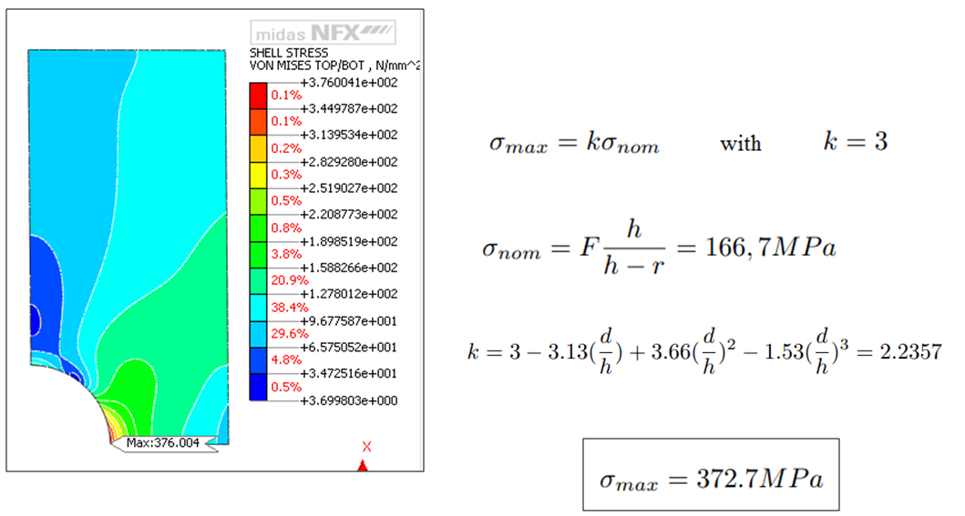
Here is the results you will get
You can observe that the Von Mises Stress results are strongly correlated with the mesh size, but this is not the only factor.
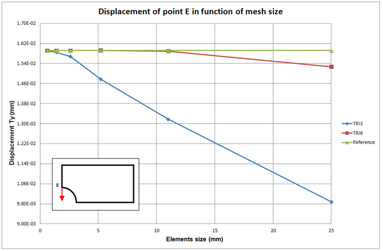
The Type of Mesh has also a very big influence on the speed of convergence.
– Simple triangular elements with 3 nodes TRI3 will almost always give unaccurate results, at least the mesh size is very coarse.
– High level triangular elements with 6 nodes TRI6 will give much better results than TRI3, because they have a middle node on each edge. the only disadvantage is that the number of nodes in the model is much higher and solver will take more time and memory space for the calculation.
-Simple quad elements are better than simple triangular elements because they have 4 nodes instead of 3, but meshing with quad element may not be appropriate for all types of geometries.
Here is a comparison graph between TRI3 and TRI6 elements to compare the convergence speed:
Let me a comment to know more about the subject !
see you next week for another interesting FEA subject :)
The problem is that a beginner even if knows about that correlation don’t have a clue how big shuld a mesh element be.
Hi guys,
AS i know, for 2D elements is not correct to use the elements size smaller than plate thickness.
It would be great if the reason behind this is explained.
Why using 2D elements smaller than the plate thickness for meshing a plate is not correct?
When choosing the mesh type, I do not care about the number of elements but the total computation time/resources. I want an accurate result in the smallest amount of time. Plotting the mesh convergence as a function of total number of nodes would be more helpful. Otherwise, of course QUAD8 > TRI6 > QUAD4 > TRI3 for a given element size.
Nice explained but i did not understand step 5. Assign the symmetry boundary conditions to the 2 symmetrical edges of the plate? what does it means can u please elaborate it ? and does fem requires 2 boundary condition one is fixed and other force applied in above case? what if i given two force as shown in fig 1 in fem , does fem doesn’t produce result ? please reply
There are 2 cases of figure:
1) You can do FEA will the full model and you should get the same results-> In this case, Symmetry is used to reduce the model size and accelerate your calculation
2) Your model isn’t actually “fixed” like in this plate example where the only boundary condition is a load applied on both sides-> In this case, the symmetry is a good way to fix your model with some kind of imaginary boundaries. You’ll have a lot of difficulties to analyze your model without symmetry here!
if laterally load is applied then how to calculate the stress ..
Sir,after applying symmetry in the geometry you have applied fixed B.C but I don’t understand why did you applied fixed B.C on horizontal edge, I think it has to be free in horizontal direction and fixed in vertical direction.
Hi This video is really helpful, I am exploring a plate with 2 holes in 2D and was wondering if I could email you directly to discuss your approach and how it could align to mine.