Today, I decided to write a post to explain simply how to perform an Analysis of the Fluid Flow inside a Choke Valve. This is a great exercise for beginners in CFD (Computational Fluid Dynamics) so I hope this example will prove extremely useful for you!
The Software I am using is midas NFX CFD: You can download the 15 days trial here
Model of the Choke Valve and Background Explanation
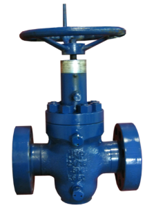
If you don’t know what is a Choke Valve, here’s the wikipedia definition
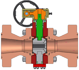
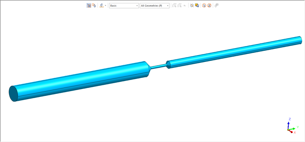
The first thing is to extract the fluid volume from the valve to get a geometric model that will represent the fluid inside the Choke Valve.
You can get this internal flow volume by different methods:
- You can create it directly using geometry tools
- You can extract it from the CAD model using a feature such as “Make CFD Volume Extraction” in midas NFX
In case you want to try, I provide the CAD file here in Parasolid Format:
Download The Choke Valve Model
Create Fluid Material and Property
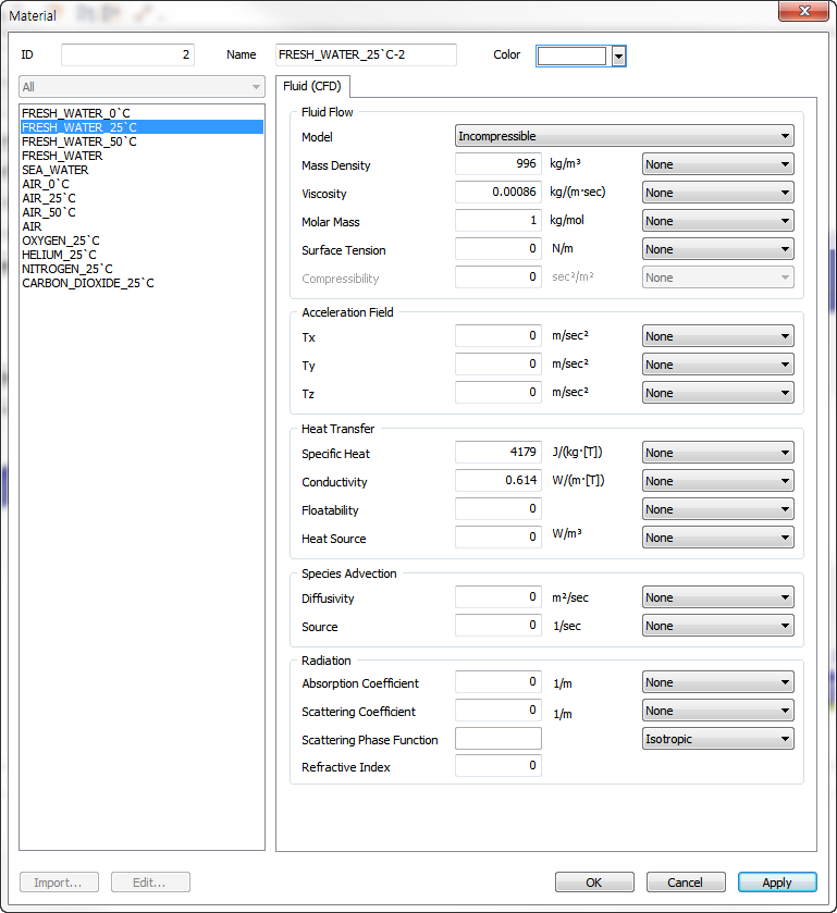
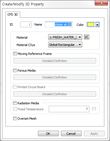
Nothing complex here. Just select the Water at 25 degreeC in the material library and select it:
The Property is the way to link the material to the mesh set:
Material <-> Property <-> Mesh Set
Note: Material is not linked to the geometry of the model.
In this case, there is nothing special to be defined additional in the property so it is very simple:
Apply the Inlet, Outlet and Wall Boundary Conditions
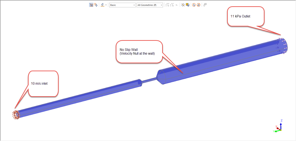
This is a very simple analysis, so I will use only 3 of the available boundary conditions:
Inlet: 10 m/s
Outlet: 11kPa
Wall: No Slip Wall condition (Velocity null at the wall)
Meshing
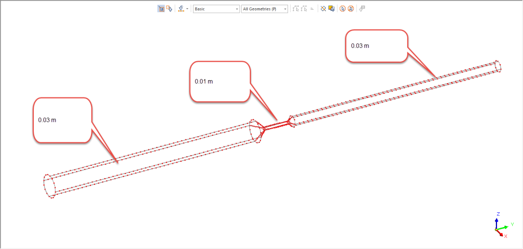
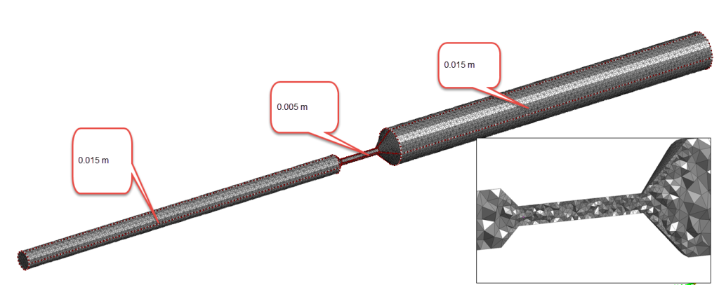
Let’s use first the Size Control to control the Size of the mesh on different parts of the geometry:
The central part is thinner and thus requires more mesh elements
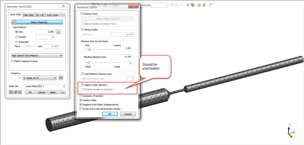
Now I can use the 3D automesher to get the mesh.
Important Note: Be sure to unactivate the “High-Order Element” Option which are not supported in CFD Analysis.
Create an Analysis Case and Launch the Analysis
Now that the model is set-up, the only thing to do is to create an analysis case.
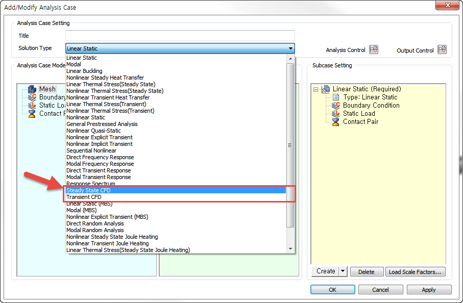
You have the choice between Steady State CFD and Transient CFD Analysis.
Steady State CFD: This analysis is mainly used when the only interest is to know the status of the fluid at steady-State equilibrium. Algorithm will show some iterations, but the only really important thing here is the last iteration we get which will describe the equilibrium conditions.
Transient CFD: Transient CFD is used when we are interested to all the Fluid Dynamics from the start (Transient State) to the end (Steady-State).
If you want to understand more in details what steady state and transient state mean, you can read my previous blog post on this topic.
In this Choke Valve Analysis, it will be a Steady State Analysis.
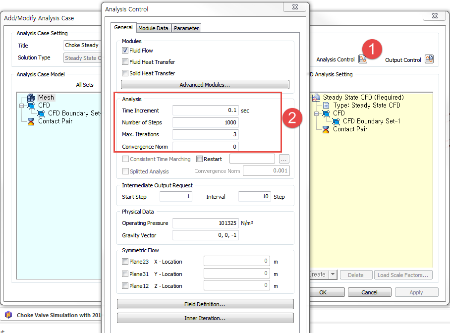
Now, one of the most crucial step is to define correctly the Analysis control options like the time increment, the number of steps. and the number of Maximum iterations.
Time Increment: in Steady State CFD, this value is not critical as midas NFX will set up automatically an appropriate time step in case your time increment is too high. In Transient Analysis, this is a critical factor that has a great impact on the convergence. It depends greatly on your model, so you’ll have to play with it to see which time increment will give you the best results (It should be enough small to allow convergence, but not too small otherwise the analysis will take too much time to complete.)
Number of Steps: This is also a critical factor because the total time of the simulation will be equal to the number of steps multiplied by the time increment. You need to be sure that Steady state will be reached during this total time.
Max. Iterations: increasing this value increase the chances of convergences at each step, but it also increase the computation time.
Now let’s compute and see what we get:
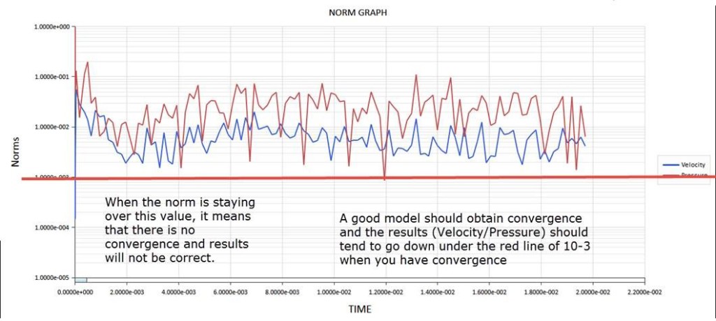
This curve appears when the solver start to solve the problem and will give you the status of the convergence in real-time.
In this case, my analysis is not converging because the norm of the velocity and the pressure stays over the convergence norm of 10e-3.
–> Model need some review to assess the problem.
Model Review and Re-analysis
I will tell you directly the solution… the mesh I created was too coarse and there was some problem to converge in the central area of the valve.
Such problem frequently happens, because CFD Analysis requires very good mesh quality.
Let’s remesh and try again
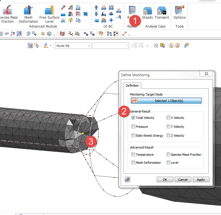
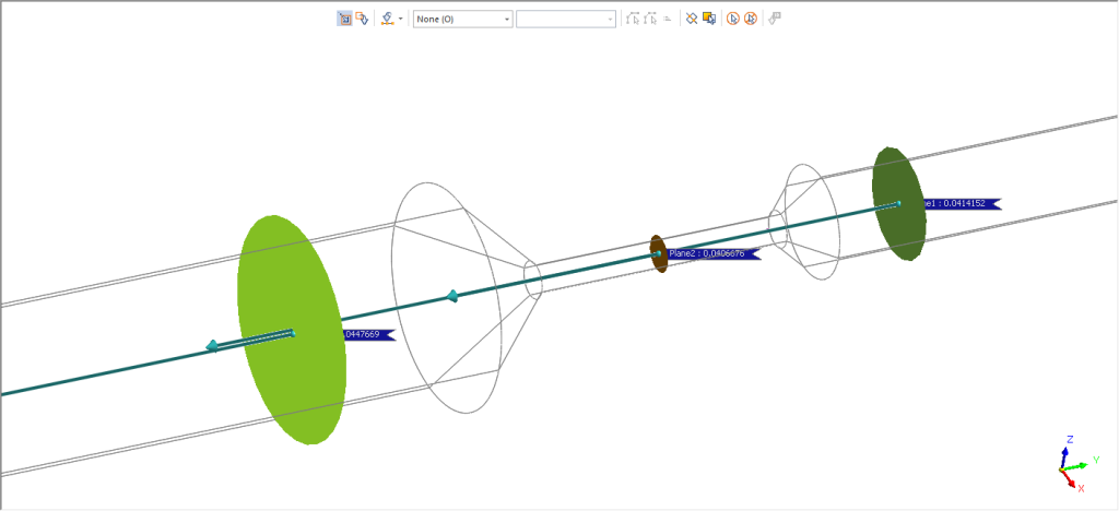
I will also define some point where I will monitor the velocity during the analysis. This is very useful to check the convergence of the velocity at a specific point.
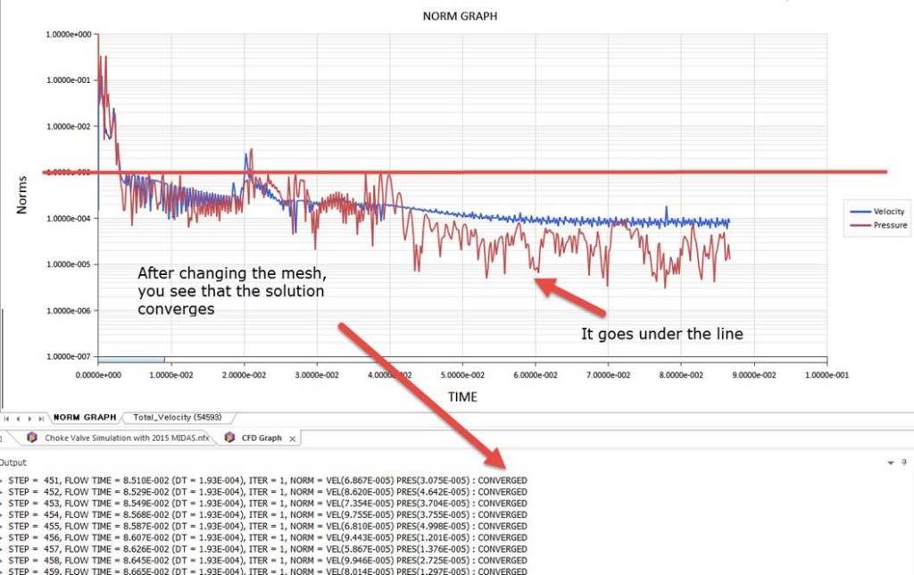
Let’s see the convergence now:
Great !! Now you can see that it converges.
Note: It is note always so easy for complex models to get the convergence and it requires to think a lot what is not physical in our model.
Some help:
- Check if the mesh is good enough
- Check the Mesh quality
- Maybe Time increment is too high
- maybe you can try with more Max. iterations
- Check if you boundary conditions are correct (Unit problem, etc…)
- …
Analysis Results
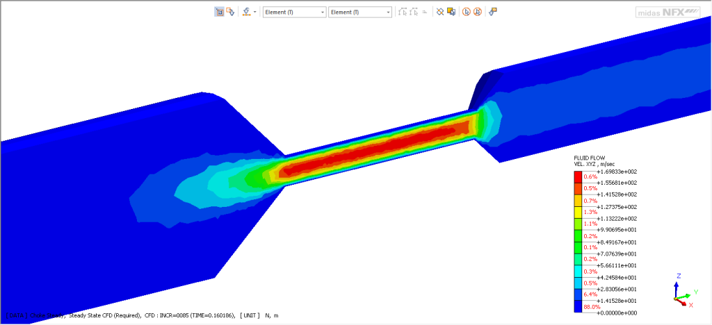
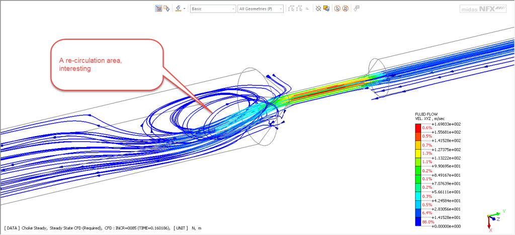
Here you go. Let’s take a cut of the Choke Valve to look at the velocity
Let’s calculate the flow quantity:
Any question or remark about this analysis? Let me know in the comments !
Hope this was useful
–Cyprien



HI Cyprien! Which methodology does Midas NFX use tô solve CFD problems ? Finite Diference Methods, Finite Element Method or Finite Volumes ? Thanks.
Hi Anderson, midas NFX uses the finite element method to solve CFD problems. From what I heard it is slightly unconventional because most CFD codes use finite difference or volume methods… but the advantage is the supposed gain in accuracy (providing your model is well-meshed…)
Really nice blog.
Very helpfull to understand physics.