I did a small research on the internet about the best FEA meshing practice and this is the kind of advice that I found:
//////////////////////////////////////////////////////////////////////
« Meshing is not important as long as you get the correct boundary conditions »
« Meshing is critical to the accuracy of your results »
« most FEA Software Automeshers do already a great job, so you don’t have to worry about that. »
///////////////////////////////////////////////////////////////////
After reading all this…my head hurts…seriously…
How can you believe something and its contrary…someone must be wrong.
What if for example, I do have correct boundary conditions, but my mesh isn’t great…would I still get good results?
(Such a question can prevent you from sleeping at night… especially if you have an important project to finish soon…)
Now… there is only one way to know if mesh really does have an impact or not…TESTING.
Here are 4 simple test models that I created:
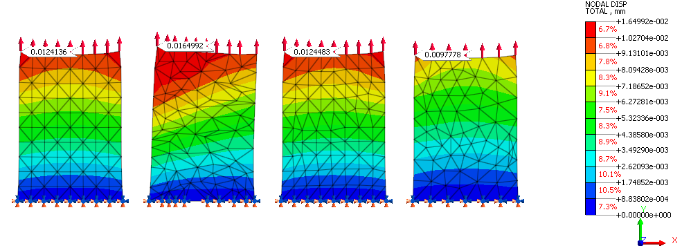
4 plates of 1mm thickness, same boundary conditions, all fixed at the bottom, all are loaded with the same 200N force applied at the top.
The only thing which is different is the meshing. I meshed the first model with a grid mesh, then I meshed the second model node by node in a very obviously wrong way and I meshed the two other models in another way to check if there is some difference. I kept more or less the same mesh size.
Now… here are the results I got for the total displacements:

I think that the answer to my question is pretty obvious… the meshing has a pretty big impact on those results (and much more than I actually thought). The total displacement in the 2nd mesh is 33% higher than in the first one and it is 22% lower in the 4rth mesh.
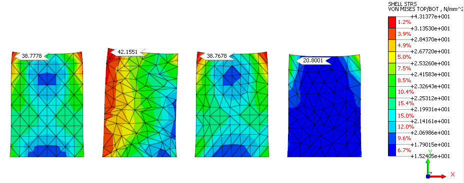
The Von Mises stress results are also quite demonstrative of the difference between the 4 different mesh sets…

NOW…Would you consciously mesh your model like that??
You probably won’t (and me neither)…
BUT…sometimes things are more tricky than we are used to and we may get a wrong meshing without even knowing about it.
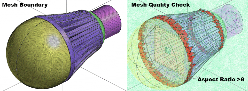
For example, sometimes you think that your 3D solid mesh is okay by looking at the external boundary…when it is actually pretty bad inside.
Here’s an example:

We are all fooled (sometimes) by the appearance of something…but as an engineer, I am convinced that we should take the healthy habit to look deeper inside and detect the hidden problems.
It’s comforting to tell ourselves that we have some powerful software available that will do everything for us but that’s just not true because a software is just a tool.
Sometimes, if you want to do something good, you have to work on it a bit more to understand what’s behind the mirror.
— Cyprien

PS: I’ll write soon about the major problems that people have with meshing… I am sure you will find it interesting, If you are interested by this topic, let me know in the comment section
Ah, the joy of the Internet :D I often see the claim that it contains all the knowledge in the world – except that it really doesn’t. For engineering problems, it’s often downright useless.
Anyway, some mathematical perspective to this problem: of course meshing matters! A lot, in fact. After all, the idea of FEA is to approximate the unknown solution function with a set of known functions. Since these known functions are defined by our mesh, its quality is of utmost importance.
There are basically two factors to consider:
1) The mesh has to be dense enough. In general, denser mesh = more accurate solution.
2) …if the mesh is “good”. In practice, elements with large angles seem to be the most harmful kind.
Of course, we cannot really define the mesh indefinitely if we want to get a solution in a reasonable time. So again, user experience is paramount :D
Great comment Antti! Thank you for taking the time to make such a thorough review ;-)
Hi Cyprien. I have known about this for thirty years and have often written about it to clients and colleagues. I am glad someone has said it in the open.
Steve
Thank you Steven! Why do I get as well the feeling that I already said that thousand times, but there’s still a lot of people who don’t know it ? ;-)
I recommend analysts always run some problems where the answers are already known, then vary some of the parameters and note the effect. Sometimes, this simple practice can bring great rewards.
That’s a great idea. Nothing replaces testing to understand better how it actually works
Hi Cyprien, I would like to know about if there is any difference when the mesh for the model is used for fluid dynamics or structural analysis. Is there any special consideration?
Yes, there are some differences. CFD generally requires much better mesh quality than structural mesh.
Checking the flow of the mesh will always avoid the issues which you have quoted. But any way thanks for listing the issues due to inaccurate mesh.
EVERYBODY needs to understand this about FEA. In the “good old days” we made our own mesh and, to a large degree, knew it’s limits and strengths. Today it’s really hard to know if the auto-mesh is really working the way we think it is. Consequently we spend more time looking at the results than the input, but may not be able to see the problems readily.
Thanks Martin for your comment! I agree 100% :)
We still use manually generated meshes (or rather, parametrically generated) when modelling electrical machines :D They have a very high level of symmetry, but automatic mesh generators normally fail to utilize that.
I am new with the FEA with Solidworks and really thought about this problem and cannot find an appropriate way to solve.
You have a very interesting way, waiting for the solution…?
If there is an analytical solution for the given problem, the mesh refinement procedure will converge towards this exact solution. However, there are situations where the solution does not converge with mesh refinement. Stress singularities are one of these situations. A mesh sensitivity study is a simple way to check potential singularity points in the mesh. Stress singularities do not affect displacement results, not even at the singularities.
I usually do some crude thinking when a complicated geometry comes in front of me…I just simply remove all unwanted features out of it. Aim should be to have simpler geometry. Sometimes I go few more steps ahead and remove few more features from my geometry. I my idea is I want to see what happen to results with this feature and without this feature. If adding of that feature making your results unrealistic which means something serious wrong could be with mesh and we need to closely investigate something around this feature.
Also we need to be little careful and clear understanding between stress singularity vs stress concentration factor. A stress concentration is a place of the mesh where the stress raises above the applied nominal stress. It behaves in a similar fashion than stress singularities, but the stress will converge towards a finite value.
I personally believe every time and each moment lot of or almost each FEA problem can be solved if keep our common sense intact. almost 70 percent FAE problems can be solved without using complex maths.
Meshing quality is directly proposnal to fea results.
Asnsys’ documentation says, and proves with examples, that the Tetrahedron is a better mesh than Hexahedron → faster and more accurate results for the same number of node. But I’ve seen many people say that the Hexahedron is a much more accurate mesh (less error for the same number of nodes). Anyone knows who’s right?
So, you still believe what software vendors tell you…? ;-)
Do your own tests and you will see that hexahedron are much better in term of accuracy of the results than tetra(1st order) because the interpolation of the stress in quadratic
hello cyprien,
how to define aspect ratio related to mesh? Is aspect ratio changes from one element to another say example tetra to hexagonal elements ? How to calculate aspect ratio these for each element .
finally , your blog was very interesting.
Hi Ajay,
The aspect ratio is the ratio of length of the longest edge divided by the length of the smallest edge. The best is when it is closed to one, which means that all edges have approximately the same length. More it grows and more it means that you have a very deformed mesh element.
This mesh study was made with first order or second order elements??? It woul be interesting to know if both meshes behave similar…