If you ever started to do linear static FEA Analysis, you probably encountered the following singularity error:
ERROR [2007]: FACTORIZATION FAILED DUE TO A SINGULARITY AT TRANSLATION-X OF NODE 111 (RANK=5262)
What is the cause of this singularity error?
This error is generated when matrix decomposition cannot progress any further due to the presence of singularities. Such errors often occur when constraints to the analysis model are insufficient.
What does it mean?
Linear static analysis algorithm can be summarized as a simple stiffness matrix inversion process.
To do this operation, the software is using an algorithm called LU decomposition.
This algorithm usually works well…except when it doesn’t.
To be able to complete the inversion process, the matrix has first to be “inversable” (not sure it’s written like that in english)
But all matrix aren’t… and matrix that aren’t inversable are called “singular matrix”.
So if you matrix is singular, LU decomposition doesn’t work and the algorithm cannot complete the process.
Why does the matrix becomes singular?
Linear static analysis is based on several assumptions and requires the finite element problem to be totally determined.
FEA linear static problem:
- Model meshed with finite elements
- Model must be fully constrained in all degrees of freedom
Assumptions:
- Material model is linear elastic and we assume we always stay in the linear elastic region (Hooke’s Law)
- Deformation must be small
- Boundary conditions must not change
- Loads do not vary in time
- Inertial and damping forces are ignored
The most important condition in order to avoid a singularity error is to make sure that the model is properly constrained.
How do I constraint properly my model?
- 1) Visualize how your physical model can move in reality in translation and rotation.
- 2) Which part is fixed?
- 3) Is it really fixed of is it pinned?
- 4) Where is the model fixed?
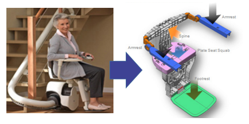
Ask yourself those questions and make some assumptions about how would be the best way to constrain your model.
Be careful with assumptions, they may be wrong. So you have to check them. In some cases, it is not obvious to determine the proper way to constraint a model.
Are there other reasons that may cause singularity error?
Obviously yes, a problem in your boundary conditions is the most probably cause of error (90% let’s say), but there are other possible problems as well.
Singularity may be caused by a problem in your mesh for example.
If you see that the node number indicated in the error comes from inside the model, rather than the boundary, this is probably because the singularity is caused by a mesh problem.
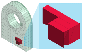
What happens frequently is that the geometry of the model is not correctly prepared and you have small edges or surfaces that create some problems during the meshing.
The mesher is also an algorithm and it can do wrong things if it gets the wrong input…i.e. the wrong model geometry.
Read this article for more details about how to improve your geometry: http://feaforall.com/2013/04/21/cad-model-simplification-for-fea-analysis/
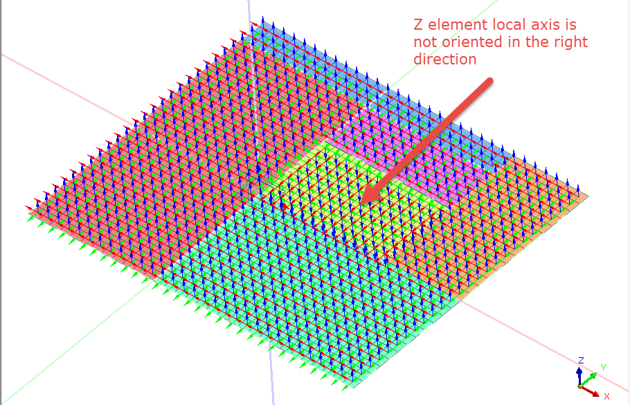
Another possible source of singularity errors that I found was when I was using a 2D FEA model.
A found the source may also be that the direction of the plate elements
Check for mesh quality and mesh result accuracy
When you perform FEA analysis, you must always be sure your mesh quality is correct.
You can check that by verifying the aspect ratio of your mesh elements.
Here is an interactive tutorial showing you how to check mesh accuracy:
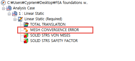
You can also check the error in the stress results by activating the result type called:
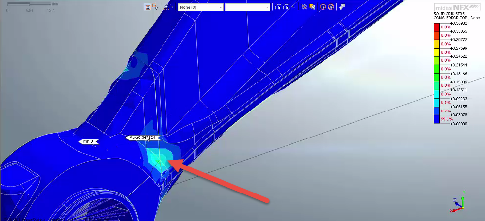
Are there any steps to correct quickly a singularity error?
- Add suitable constraints by adding SPC (Single-Point Constraint), MPC (Multi-Point Constraint) or rigid body elements in order to eliminate any singularities.
- The error may be generated if contacts are not properly defined in the analysis model. In this case, check if all the contact conditions between the parts have been defined, and also if the “Contact Tolerance” value has been defined to include the tolerance distances between the parts.
- In case of elements that include DOFs associated with no stiffness, use the “AUTOSPC/Automatic Single-Point Constraint” option or other appropriate constraints to eliminate the singularities.

Very well explained.
Many thanks to the author.
Thank you Sergey! I am glad you enjoy the article!
Great insight into Singularity error. Learnt a bunch of new stuff!
Really great article. thank you!
Cyprien your blog helps me a lot to understand all concepts related to FEA, how to tackle the problem.
I hope you will be god of FEA in future.
If every new comer in FEA field read your blog I guaranty they will never scratch there head
That’s an awesome comment! Thank you so much! So few people are telling me that they like my posts so I am always wondering if it really helps… thanks.
That is a clean and neat explanation.. Thank you :)
Hello sir, your articles are amazing, it really helps me alot. Your articles changing my view about FEA…Thank you
Loved it!!
Thank you, your posts are really helping
Thanks for mesh quality check brief video
Thank you so much for this article. It helps me to understand some issues that I face.
Very well explained. Thank you.
Well explained. It is really helpful. Thanks for sharing.
Best explained sir. But I have a query. I am a beginner and when I perform eigen value analysis GRID POINT SINGULARITY ERROR occurs at all mid nodes(second order element). Can you tell why.