I started some weeks ago to talk about FEA simulation in the acoustic area with this article… and I am just starting!
Today, I wanted to present to you a “new” type of electronic device that you can simulate in FEA: Filters!
(Ok, nothing new about filters… they have been here for decades! But being able to simulate them in full 3D is actually pretty new in the FEA area)
In this article, I plan to talk about the main things you need to know about filters first so you will understand better afterwards the underlying challenges that you need to address when you design such devices!
What is the link with acoustics?
Certain type of very cost-effective filters called Surface Acoustic Wave Filters (SAW for the intimates) are using both acoustic waves and the piezoelectric effect combined to filter signals
… and Yes, I’ll tell you how to simulate then too in FEA!
Just keep reading until the bottom of the article ;-)
Ok, first things first…
What is an electronic filter and why should I care??
You probably didn’t realise it, but you have already more than thousands of filters in your life!
They are everywhere:
- Your mobile phone
- Your computer
- Your television
- etc…
If we didn’t have filters, we wouldn’t have all of that amazing technology which allows us to speak instantaneously which other individuals at hundred of kilometers away…
So basically, if you have a signal, you have a filter to modify and improve that signal going with it :)
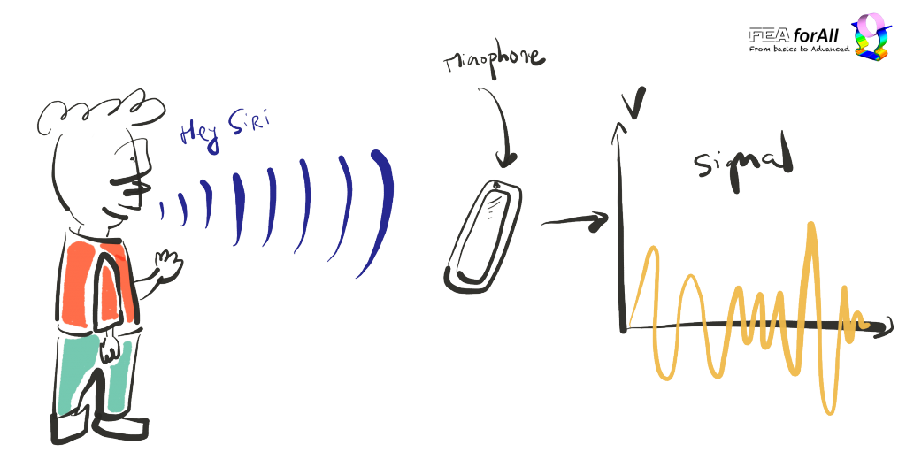
By signal, I mean the voltage in function of time received by a microphone after reception of a voice acoustic wave for example
BTW, microphones are also called by the beautiful name of “electro-acoustic transducers” because they are a device which “transduce” (understand transform) an acoustic wave signal into an electrical signal that can be transported somewhere else.
Check this nice wikipedia article if you want to know more about transducers
Ok… back to the initial question:
What is a filter?
A filter is a device which process a signal by removing some “unwanted” components inside it.
Signals are like everything on this planet… they are not perfect!
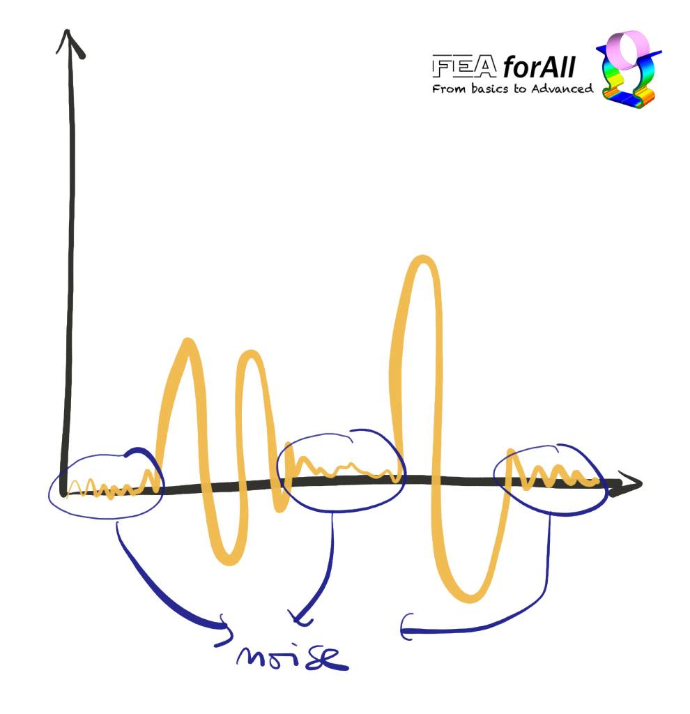
A signal often(always) come with some noise for example…
When I record videos for my Youtube channel for example, I often get some disturbance in the background (A clacking door, the freezer, a guy playing with an electric drill on the floor above, or even my Chinese Mother-in-law asking if I ain’t finished yet… don’t laugh please, that’s not funny)
Would be nice to remove this kind of noise from the signal and get it “cleaned up”, right?
Well, that’s theoretically possible!
… Using a filter of course ;-)
How can you remove a part of a signal with a filter??
To explain you that, I have to make a quick but necessary aparte in the frequency domain!
We generally tend to think about a signal as a temporal function like that:
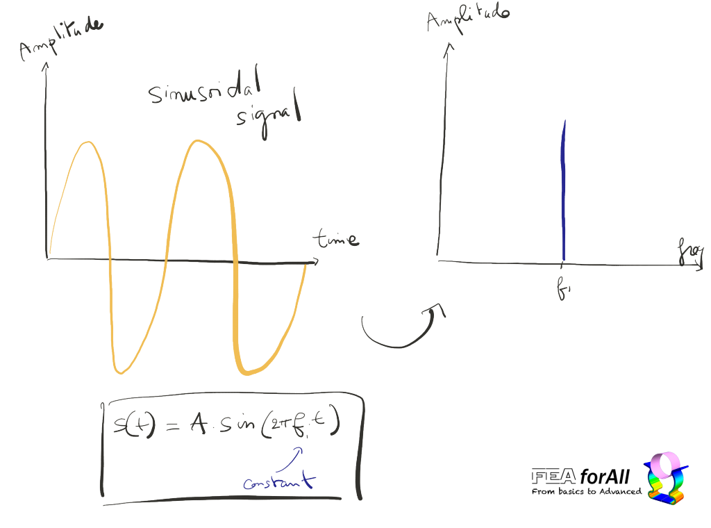
Actually, a signal can be view under another “angle”… by its frequency distribution :)
Time Domain and Frequency Domain are very close from each other:
Every signal you see as a function of time can be seen also as an infinite sum of harmonics each with its individual frequency multiplied by a coefficient.
And, wait for it… there is even a name for that :)
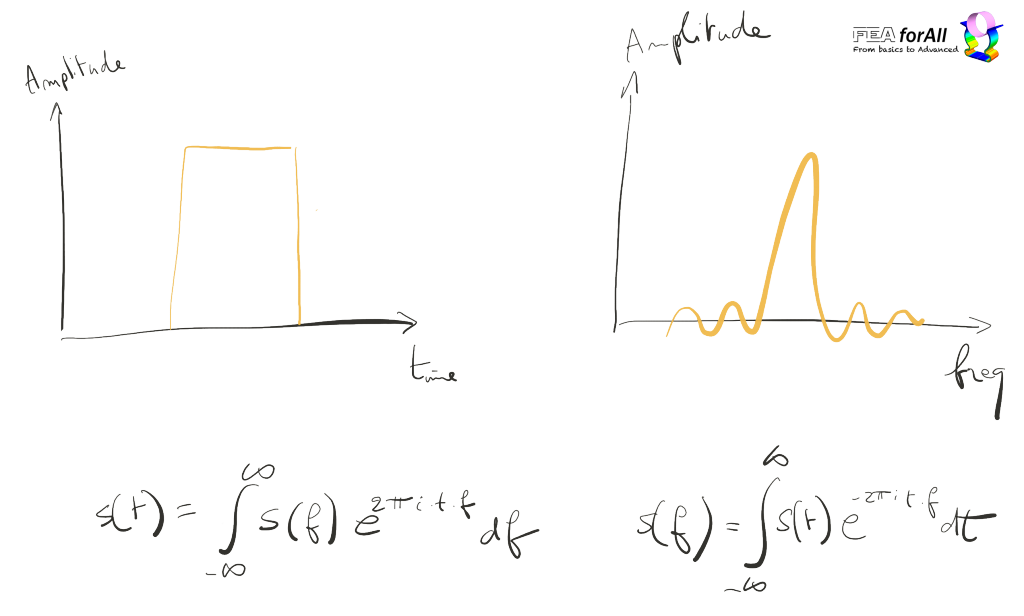
That’s called the Fourrier Transformation !
And when you want to get back in time (seriously), you can use the inverse Fourier Transformation
isn’t that cool?
I used to LOVE this formula a few years back…
It’s amazing to see how a time domain signal gets transformed into a frequency domain signal!
BTW, if you play with the FFT for some time, you will discover with amazement that a perfect time signal translates itself in an INFINITE number of harmonics!
It reveals why no signal in reality is perfect… it is just not possible.
By the way, if you want to know how to do the FFT of a time signal in OnScale on your simulation model, you can watch this video:
Ok, back again from this little digression about the Fourier Transformation…
How does the filter modify a signal to remove some part of it?
Take a look at this time response signal that I got from this SAW Unit Cell Model:
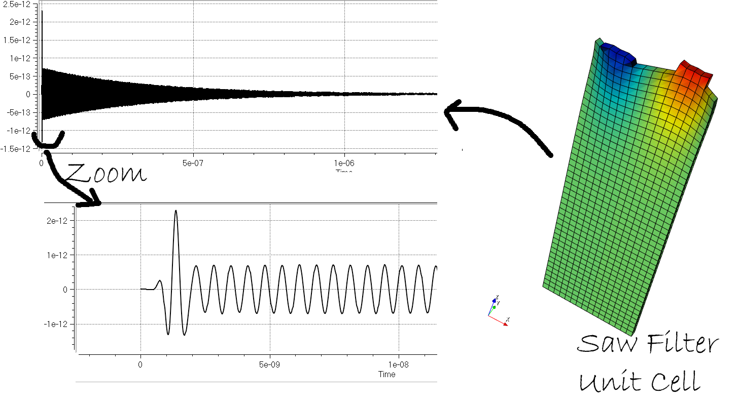
You don’t see anything…
After FFTing it into a frequency signal, you will see something like that:
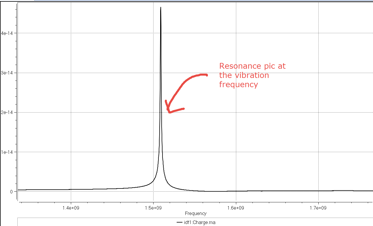
Much better right?
Now, You can see clearly the charge pic at the resonance frequency!
But… where is the noise?
Humm… you got me here
This model is too simple, so you don’t see the noise…
In reality, you would get something more like that:
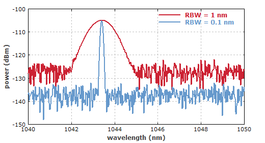
@credit:rp-hpphotonics.com
The lowest frequencies are generally attributed to noise!
And an important factor in filter design is called (wait for it)….
The signal-to-noise ratio!
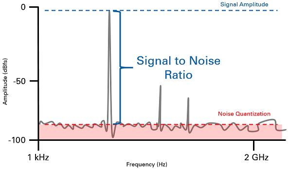
@Credit: mtechprojects.org
You understood that I want to remove this part of the signal I guess..
Well, you can do that with a particular type of filter called a High-pass filter !
Like the name indicates, it will only let the frequencies higher than a certain cutoff frequency fc go through.
What’s a “classical” high-pass filter looks like?
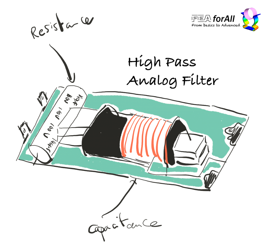
If you come back in time, you will probably see electronic high pass filters like this into old devices:
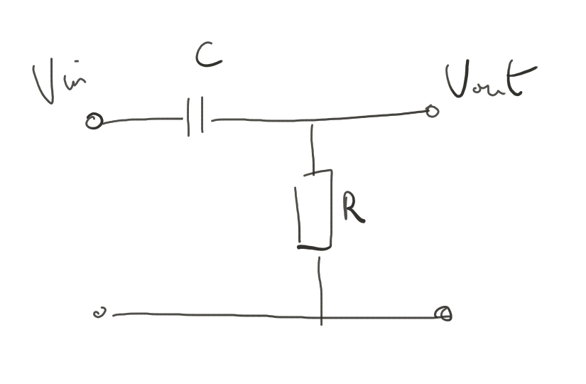
Such filter is an analog, first-order high-pass filter realised by a simple RC circuit such as the following:
The cutoff frequency fc can be calculated by the simple formula:
fc = 1/(2*Pi*RC)
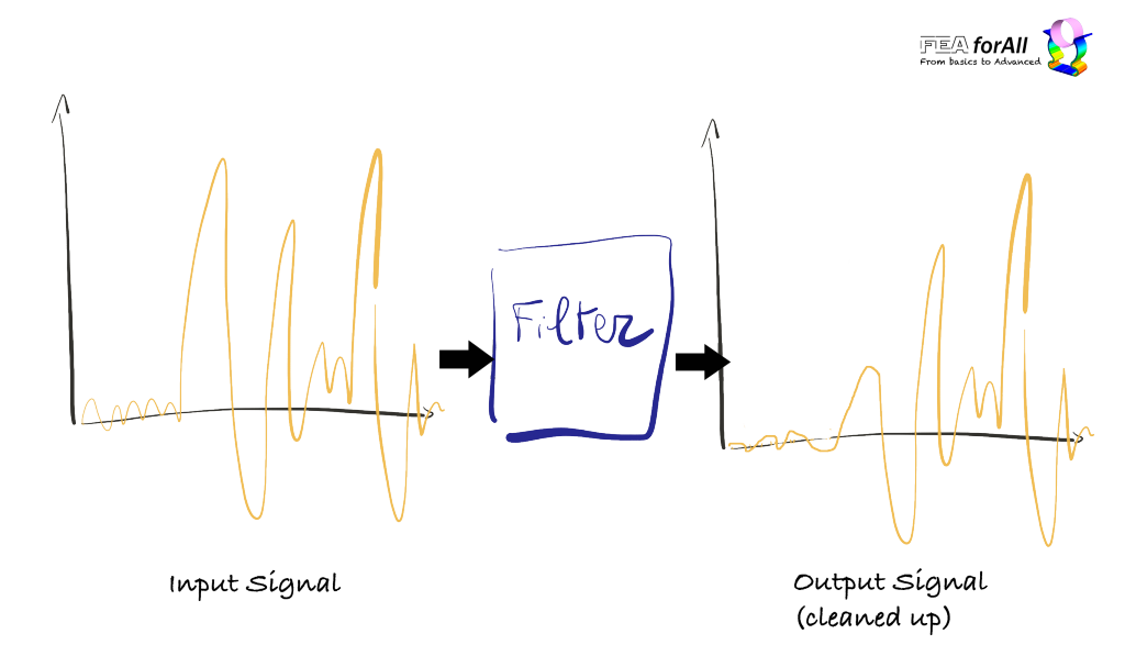
You can think about about this filter as a black box in which you input your signal to be processed… and which gives you back the cleaned up signal where the unwanted low noise frequencies have been removed.
Are there other types of filters?
You bet… !
You have filters to do almost everything you want to a signal :)
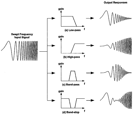
- Low-pass filter – low frequencies are passed, high frequencies are attenuated.
- High-pass filter – high frequencies are passed, low frequencies are attenuated.
- Band-pass filter – only frequencies in a frequency band are passed.
- Band-stop filter or band-reject filter – only frequencies in a frequency band are attenuated.
- Notch filter – rejects just one specific frequency – an extreme band-stop filter.
- Comb filter – has multiple regularly spaced narrow passbands giving the bandform the appearance of a comb.
- All-pass filter – all frequencies are passed, but the phase of the output is modified.
And much more…
Here’s an interesting picture that shows the effect of those different filters on a signal:
@Credit: sensorsmag.com
There are many types of different technologies too to create filters!
The one I showed to you as an example is an antique “electronic filter” based entirely on passive components such as resistances, inductances, capacitances…
Digital filters are filters which are implemented directly in their mathematical form with algorithm and code (yes, you have that too!)
There are many more types to discover…
But let me present you just 2 of the most interesting one used intensively in telecommunication equipment nowadays… The SAW(surface acoustic wave) Filter and the BAW(bulk acoustic wave) Filter!
Those filters are called electromechanical filters, because they involve both some electrical physics and some mechanical physics.
What is a Surface Acoustic Wave (SAW) Filter and what’s the principle behind it?
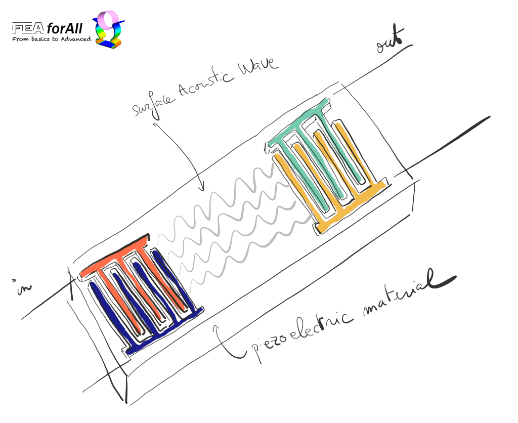
A SAW filter is basically a special type of filter which use very cleverly a propriety of surface acoustic waves to filter a signal.
The devices on both ends that put here with beautiful colors are called IDT Devices which means “interdigital device”
You can think about this IDT has a pair of fingers that tap like a drum on a bloc of special piezoelectric material called a “substrate”.
The Surface waves generated by the IDT on the left propagate on the sublayer of the substrate and reach the second IDT on the right.
This IDT is called transducer, because it transforms the electric signal applied to it on the left into a mechanical acoustic vibration through a clever coupling between the “fingers” and the substrate because of the piezoelectric material
(remember that piezoelectric material deform mechanically under a voltage)
Why is this a filter? I see only a wave created on one side, travelling on the other end?
Good question :)
The wave that goes through the substrate has a certain defined velocity (decided by the wavelength of the piezoelectric material used for the substrate).
… and the transducer is mainly effective at a frequency where the transducer pitch corresponds to the surface wave wavelength.
Thus, if you send a multi-frequency (broadband) signal, the frequencies close to the surface wave wavelength stay and other frequencies are attenuated.
Thus… you understood i think that this SAW filter acts as a pass-band filter.
Quick side note:
If the 2 IDTs are the same, then the input signal is transformed and delayed.
(The time the surface acoustic wave takes to go through the substrate takes more time than if the signal was directly travelling as an electric signal into an electrode)
This delay which varies which frequency is what was used initially to create pulse compression radars.
In the radar, the signal is swept in frequency and the filter compresses that into a short pulse.
Why using a SAW filter instead of a more traditional analog filter?
Books have been written about that… so I’ll answer very simply for now:
SAW Filter can be designed very specifically to keep only very very narrow band of frequencies and at the same time, they can limit the loss of energy created during the transformation
(In the jargon, you will hear that SAW filter is able to get you a very narrow “Q coefficient” )
I’ll probably talk about that in another article in the future.
Can you actually simulate Full SAW filters with FEA?
Yes, but only one software has been able to do that for now: OnScale.
(Because of the model size and also the fact that SAW filter models require a very good coupling between electric-piezomaterial and mechanical simulation)
Here’s a webinar in which you will find all the details:
And by the way, OnScale actually provides the model for free download here
Ok, now, that’s almost all I have for today…
(that’s a lot of info already!)
I will have more coming in the future, I hope it was useful :)
If this is useful for you, please leave a comment and let me know
Thank you so much for reading!

Thank You so much for sharing this valuable piece of information