The IGES CAD format
IGES stands for “Initial Graphics Exchange Specification”.
This CAD format was first published in January 1980 by the National Bureau of Standards with the beautiful name of NBSIR 80-1978. It originated from the ICAM project of the Unites States Air Force from 1976-1984.

This ICAM (Integrated Computer Aided Manufacturing) Project was created to develop procedures and processes that would help to integrate all the operations in the Aerospace manufacturing industry.
In short, they wanted to create CAD software that would generate automatically all the procedure required to control machine tools that would manufacture the mechanical parts in the aerospace industry (and they succeed by the way ;-) )
A big problem at the time was the incompatibility of data exported from various CAD systems (that’s not a new problem as you can see…)
Since 1988, The United States Department of Defence has required that all digital products and manufacturing information for weapon systems contracts be delivered in electronic form such as IGES format (that’s why CAE software all support this format)
The IGES format has been an ANSI format since 1980 and thus widely used in automotive, aerospace and shipbuilding industries.
Now some technical details…
The structure of the IGES CAD Format:
An IGES file is composed of 80-character ASCII records… like in the the punched card era
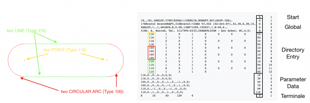
Here is a simple example of CAD model composed only of 2 lines, 2 points and 2 circular arcs that will show you the structure of an IGES File:
(Those images were taken from the wikipedia article here)
As you can see, IGES files are composed of 5 sections called respectively Start, Global, Directory Entry, Parameter Data, and Terminate. Those sections are indicated by the characters S, G, D, P, or T in column 73.
The geometric data are present in 2 different sections of the file but in different formats. They are registered into a fixed-length format into the Directory Entry section and in a comma delimited format in the Parameter Data format section.
The comma delimited format is supposed to be more readable by humans…that’s why ;-)
Want to know more about how CAD formats play a role in CAE simulation?
Read my article about CAD formats and CAE Simulation:
CAD formats: Which one is the best for CAE?
« Back to Glossary Index
Leave a Reply