If you are tackling static* problems with FEA, there is a basic tool that will help you a lot: The Free Body Diagram (FBD).
If you are trying to analyze static mechanisms, you probably heard this name before…
But do you know what it is and how it actually works?
That’s what this article is all about!
*Note: The Free Body Diagram can also be used to analyze dynamic problems if you introduce translational and rotational accelerations and velocities in your model.
What is the Free Body Diagram? Quick explanation
Mechanical systems tend to be composed of several parts or structural elements connected together in some way.
The problem is that it may over-complexity the analysis if you consider all that from the start!
That’s why engineers have found an easy way to conceptualize the structure in which all connecting parts have been removed: The Free Body Diagram
This Free Body Diagram is a useful tool in FEA analysis as I will show you in this article
How do you draw a Free Body Diagram?
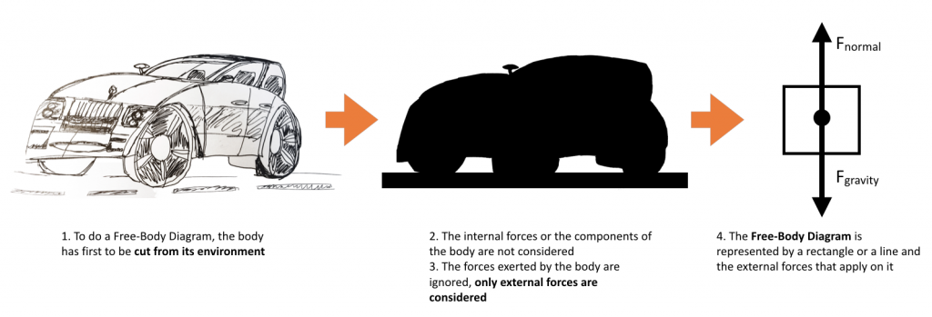
Instead of considering the real physical shape of a part, a single line or a rectangle replaces it. Nodes with certain properties or set of forces and moments represent each connection.
Nodes with certain properties or set of forces and moments represent each connection. External force vectors replace as well internal forces that exist in the system.
We then draw vectors that reflect the magnitude of the force and orient them in the direction the force is acting to have a clearer understanding of the system.
Example 1: Drawing the Free Body Diagram of a Beam
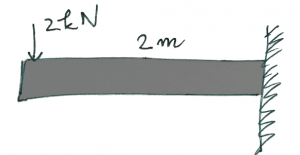
How would you determine the free body diagram for this beam?
- Replace the beam by a simple segment
- Remove the wall connection and place it by a force in X and Y directions and a Moment
- Apply the 2K force at the other end of the beam
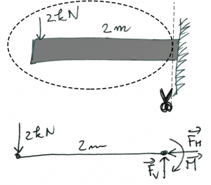
The forces and moments at the wall connection are unknown, but they can be determined if we suppose that the beam is in equilibrium because they are identical to the internal forces in the beam before it was cut from the wall.
Fh = 0
Fv = -2kN
M = 2K * 2 = 4 KN.m
For a beam, this system of equations is very simple… and so a FBD isn’t so useful.
But now consider the following systems:

The corresponding Free body diagram is like this:
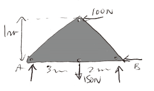
The Free body Diagram actually simplifies a lot your job here because it ONLY takes in account the external loads and constraints and NOT the internal structure.
Why is it useful to use the Free Body Diagram in FEA?
It happens ( frequently ) that the loading condition is not so simple and that we make some errors during the assignment of boundary conditions.
Those errors may result in totally wrong results…
Free Body diagrams are useful to check that we didn’t do any mistake by comparing the reaction forces that we get from the FEA analysis and the forces calculated by the Free Body Diagram.
The reaction forces (or moments) obtained from the solver at the constraint points are as accurate as the Free Body Diagram (FBD) plots produced from them.
Let me give you a useful example of the Free body Diagram
Last Friday, I was invited to give a lecture about finite element analysis to the Ecole Centrale of Lille in France and I found at the same time a very interesting FEA example where the Free Body Diagram can help!

Students had to analyze a hook and they had the following details:
Solving the “hook” problem using the Free Body Diagram
The hook is suspended from an axis in its upper part and must withstand an effort of 10000N on the lower face which has been modeled. The hook is free to rotate about its axis to orient itself according to the load.
The material used is an isotropic steel with an elastic modulus E = 200 000 MPa and a Poisson’s ratio of 0.266
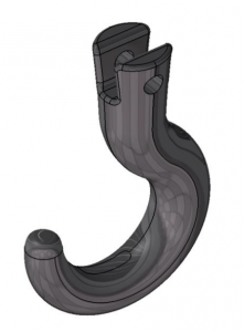
The model is very simple and the answer seems straightforward… and that was the whole point.
I saw the students rush to fix the top of the hook, to apply a vertical load on the lower face, to mesh and solve.
They got some results… but it was false!
A student found the solution
A student with a bit more reflection than the others had the idea to check the reactions at the upper part where the hook was constrained.
He then called the professor:
« There’s something strange, professor, I don’t understand why there is a moment acting at the top of the hook… isn’t the hook free to rotate? »
…And that was the whole point!
There shouldn’t be a moment there… and that was a hint to the fact that the loading of the hook was wrong.
Now, if the students had the reflex to draw a Free Body Diagram of the hook, they would have seen immediately the right direction of the loading.
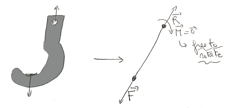
The solution was to apply the load in the same direction than an axis passing through the hole at the top.
The Reaction that you find in the software should be equal to the load applied. The moment should be zero.
That’s a good way to check that your results are correct in this example!
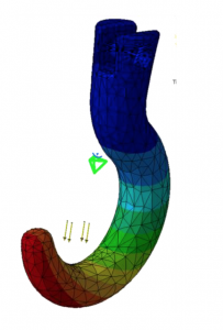
Total Displacement Plot
Ok, that’s all for today! I hope you will use also the Free Body Diagram in your FEA analysis to get better results!
//////////////////////////////////////
Do you have some examples of a meaningful usage of the Free Body Diagram in FEA?
If yes, please let me know in the comment…It will help everyone reading this article to understand better how to perform more efficient FEA analysis!
Did you like this article? Let me know in the comments and help me to share it on Linkedin ;-)
–Cyprien
Here is an article from MIT that inspired me to write this article.
Simply great! Thank you for the article…
Concept was good simple and clear
How conect two system independently so that transmit the same load for FEA?
I am not sure to understand what you mean Samir!
Dear Rusu,
Excellent. Two questions:
i) Example related to triangular geometry, once more elaboration of fixed end substitution in FBD is sought. The substitution needs to be for six degrees of freedom.
ii)You must be aware of cable net required for supporting glass facade. Manually how one can check the pretension & reaction forces?
Nice point. Another solution would be to remove the rigid body rotation mode around the axis from the stiffness matrix nullspace and solve a least squares problem.
need some more details about this topic
Need some more explanation about Hook problem.
Great article..
Thank you!!!
In general crane hook, the maximum stress will be developed at critical cross section but here it’s not developed at that place. It’s developed at the end of the hook
The picture in the article is a deformation plot, not a stress plot.
A title or legend would be best practice when displaying FEA results to avoid
misconceptions
Corrected that, thanks for mentioning it!
I have two issues:
I dont’t understand why moment must be zero. we can realize that the reaction point must have moment to keep system equilibrium for applied force produced moment on reaction point.
The other question is why the reaction force calculated by free body diagram must be fully equal to the reaction force calculated by FEM. In my opinion,computing reaction force is based on equilibrium theory. In this case, the structure is conaidered as rigid(no deformation). But in stress analysis, the structure is deformable. So the reaction force conputed from two methods isn’t fully equal.
I think the reaction force conputed from two methods having little difference is normal.
Very good explanation. Great!!