I love to answer questions from the readers of my blog… especially when they are good. This one is about CAD formats, let’s tackle it ;-)
This question here from Mrinal is a question that I asked myself a lot too…

So…
Why not writing an article to explain the whole stuff to CAE beginers? (and everyone else who wants to understand)
Understanding how CAD formats works will help you to avoid a lot of headaches
As you know maybe I worked for several years into a technical support team of the CAE software
…so I saw a lot of strange stuff and especially about the CAD models…
Engineers want to import all kind of CAD models
And, as you may expect it, most of the time it doesn’t work as expected…
And unfortunately my job was to find why T_T
I always remember this clients who sent me the CAD file of a small pleasance boat and then told me:
« Why can’t I open it with your midas NFX software when I can open it with Abaqus? »

That’s the kind of eternal question I received all the time…

(if you worked in tech support, you probably know this feeling…)
Anyhoo…
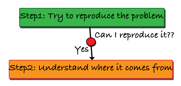
The first thing to do is always the same
Try to reproduce the problem and try to understand why it doesn’t work properly if it actually doesn’t

So that’s what I did
Step 1: Reproducing the problem
I imported the model
It didn’t work
I tried with the student edition of Abaqus,
It imported the model
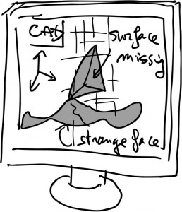
…but there was a big problem inside
Some parts were missing… And others where highly deformed

… Definitively not what you would expect from a CAD model import function
That’s when I understood that the problem lied in the CAD model rather than in the software
Step 2 – Understanding where the problem comes from
Time to change the gears and go in the second mode: Finding what happened and why
This discovery helped me to understand how a CAD model file actually works and that’s why I decided to share that with you
Let’s summarize:
( Having a clear understanding of the problem statement is always key when you want to solve a problem…)
The CAD was being imported in Abaqus, but some shapes were highly deformed or missing…
It was not importing at all in midas NFX…
And the client wanted to know why…
WAIT
There was something that the client omitted to mention…
(the solution often lies in what is NOT told…)
Where did this CAD file actually come from…??
That’s only when I started to ask deeper questions to the client that I started to understand…
The client had his own software to analyze small boats and he was generating himself the shapes and then saving the file into a standard STEP format
Bingo
After searching on internet, I finally understood why it couldn’t work…
But first to understand that, you have to understand (1) what is a CAD file and (2) how data of a geometric model are saved.
That’s why I will explain that to you first…
Stay with me ;-)
How is data saved into a CAD file?
The thing about graphical software is that it is very heavy on visual and geometric shapes
That makes it difficult to save or exchange the data …
Why is that?
Because most of the communication systems and channels that we build are based on text and words, not on visual things
If someone asks you what is inside a picture, you answer him with a word… That’s a « XX » inside the picture
Now, that’s much more difficult if you want to describe the actual picture point by point in order for that person to understand clearly and visually.
So…
You can say that trying to send a CAD model to another software is like trying to make an elephant go into into a pipe

Fortunately for us, geometric models can be decomposed into pieces and reconstructed without any harm (well, that’s what we’ll see here ;-) )
and BTW… this trivial but essential problem also explains why we didn’t invent teleportation (yet) ;-)
Let’s do a small thinking experiment together:
If you had to tell someone everything about the geometry of your model without ever actually “showing” him, how would you do that?
Here’s what I would do
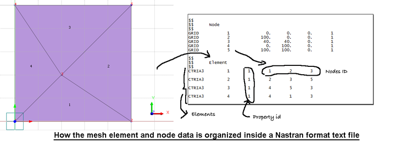
I would take each basic components of my geometry one by one and I would try to describe it using pure geometrical coordinates.
A finite element model is much more easy to decompose like that than a pure cad model because it uses only very simple shapes
Let’s try… I made this video just to explain what I mean
Video: Understanding how the data of a Nastran file are structured
So, as I demonstrated in the video, this is how the geometry data of the mesh is interpreted:

Ok, now you understand what is a file of data and how data are actually saved inside
Such files are used everywhere and especially in FEA where you need a simple way to make an interface and communicate between the graphical interface, the solver and the results
The problem we have now is the following…
Who decides how to construct this data file?
Well… of course you… the software developper I mean
Because of that companies have all created their own formats which all have their particularities
Now back to my initial story
Why the file didn’t open?
Because it had been generated by a very non standard process and was including some NURBS curves that are not supported by CAE and cad software in general
You see, to export and import a CAD file, you need 3 things:
• The geometry itself in 1D 2D or 3D
• A system that will decompose the geometry into a data file
• Another system that will read the data and recompose the geometry from the file (sometimes called a « CAD translator »
The problem is that the system that recompose the file often doesn’t use the same technology that has been used to create it…

The main reasons are that:
- Every company have their own proprietary technology and develop different ways to solve the same problem
- Those different systems are often not compatible between them
So if you export a DXF format from AutoCAD for example and you try to import it with Solidwords…
The result is often the same than trying to translate english into chinese with google translate and then translating back chinese into french and then into english… (your 2 english sentences will probably be totally different… I let you try)
So… The big question now…
What is a NURBS?
(No, it’s not the same than a NERD)
NURBS are normally used in graphical applications such as Maya or 3D studio max were they are useful to represent highly complex visual models (Realist game characters, etc…)
BTW, the “fancy” name NURBS comes from Non-uniform rational B-spline… but everyone knows that, right? ;-)
And here is the answer to my CAD model translation headache:
Because those NURBS curve weren’t supported they were basically ignored, deformed or deleted in a Abaqus while in midas NFX the file couldn’t simply be opened
If you want to know more technical details about NURBS Curves, here is a good article about it on wikipedia.
Side note: CAD formats are a business for some companies because one side of the companies want to limit the exchange of data between their software and others, well… the other part of companies provide solutions to overcome those cad formats conversion problems as you may expect.
Introduction to the different CAD formats
This article won’t be complete without a short but impactful description of the main CAD formats used in CAE simulation, isn’t it?
Let’s talk first and foremost about the standard formats…
The IGES CAD format
IGES stands for “Initial Graphics Exchange Specification”.
This CAD format was first published in January 1980 by the National Bureau of Standards with the beautiful name of NBSIR 80-1978. It originated from the ICAM project of the Unites States Air Force from 1976-1984.

This ICAM (Integrated Computer Aided Manufacturing) Project was created to develop procedures and processes that would help to integrate all the operations in the Aerospace manufacturing industry.
In short, they wanted to create CAD software that would generate automatically all the procedure required to control machine tools that would manufacture the mechanical parts in the aerospace industry (and they succeed by the way ;-) )
A big problem at the time was the incompatibility of data exported from various CAD systems (that’s not a new problem as you can see…)
Since 1988, The United States Department of Defence has required that all digital products and manufacturing information for weapon systems contracts be delivered in electronic form such as IGES format (that’s why CAE software all support this format)
The IGES format has been an ANSI format since 1980 and thus widely used in automotive, aerospace and shipbuilding industries.
Now some technical details…
The structure of the IGES CAD Format:
An IGES file is composed of 80-character ASCII records… like in the the punched card era
Here is a simple example of CAD model composed only of 2 lines, 2 points and 2 circular arcs that will show you the structure of an IGES File:

(Those images were taken from the wikipedia article here)
As you can see, IGES files are composed of 5 sections called respectively Start, Global, Directory Entry, Parameter Data, and Terminate. Those sections are indicated by the characters S, G, D, P, or T in column 73.
The geometric data are present in 2 different sections of the file but in different formats. They are registered into a fixed-length format into the Directory Entry section and in a comma delimited format in the Parameter Data format section.
The comma delimited format is supposed to be more readable by humans…that’s why ;-)
The STEP CAD format:
STEP stands for “Standard for the Exchange of Product model data”.
The STEP Format stems from an ISO Standard, and are specifically the ISO 10303, which is an ISO standard for the computer-interpretable representation and exchange of product manufacturing information. This ISO standard is used to represent Objects with 3D CAD models along with their related information.
The STEP format started to be developed in 1984 as a successor of IGES format…and the main purpose was to represent all the information of a product inside one unique software-independent product model file.
In the following years, the capabilities of STEP were widely extended, primarily for the design of products in the aerospace, automotive, electrical, electronic, and other industries

The STEP format is maybe THE format of reference for CAE simulation as it is a standard in itself for the industry.
I won’t detail here the structure of the file because it is much more complex than a simple text file… in fact you would need to learn several languages of programmatic to understand how it works (The EXPRESS language used to generate STEP files is based on other languages such as Pascal, ADA and C++).
You can learn more about it from this wikipedia article if you are interested.
The PARASOLID CAD format:
Parasolid is the name of a geometric modelling kernel that was originally developed by a company called « Shape Data Limited », but then it was purchased by Siemens PLM Software.
This geometric modelling kernel can be licensed by other companies to use its functionalities inside their 3D CAD or CAE software products.
This parasoled kernel will provide some functionalities « ready to use » for 3D geometric modelling such as boolean operations, feature modelling, surfacing, thickening and hollowing, blending and filleting, sheet modeling… etc…
The most common extension you will find for a parasoled file is the extension .x_t (parasoled files exported from CAD have this extension).
There is also another binary format .x_b which is more machine independent and not subject to binary-to-text conversion errors.
If You want to know more about the parasolid CAD format, you can read this article on wikipedia
—-
I still have a lot to write about CAD formats, but that’s just too much of a task to write EVERYTHING in one article…Next time I will add more formats and details
—
Now the last questions to answer…
Which of the CAD Formats is the best for CAE?
As you may expect, there is straightforward answer like “XX format is the best” (unfortunately)
You understood through this article though that there is a difference between different CAD formats.
The main difference lies in the way the geometry data is actually represented inside those CAD text files and what “can” be represented.
It is important to remember that most CAD formats don’t support curves such as NURBS ( or other complex shapes used in the graphic design industry)
Mechanical products tend to be modelled inside CAD software and not inside “non-standard” graphic design software products
(I am talking about software such as Maya or 3D studio Max here).
Finally, there are CAD formats that are standard such as IGES and STEP formats.
Those formats are great because they are supported by all CAE software as a way to exchange model information (they were created for that)
There are also proprietary CAD formats developed by software vendors to suit their own needs (Solidworks, Catia, Inventor, Parasolid,…).
Proprietary CAD formats are useful for vendors because it helps them to store data more specific to their software and it is also a way to protect their technology of course…
but that come at the expense of the inter-exchangeability between different software platforms.
Ok…That’s all for today!
Other Article Related to CAD Formats:
/////////////////////////////////////////////////////
You maybe noticed that I wrote a lot of great educational article… that’s because I really want to contribute and help engineers who are new to FEA to understand those concepts better and faster!
I am not hiding that it takes a lot of efforts to write all that, so…
If you like this article, there are 3 things you can do for me:
1- Help me to share this article on Linkedin, facebook, twitter or in your habitual forum to help more people understand CAD formats (use the share button on the left of the article).
2- Let me know in the comments what you learned from it and what you would like to learn even further so I can write more on the topic
3- Join the newsletter (if you are not already subscribed), I’ll send you everything I write (and much more) by email!
Thank you for reading!
–Cyprien
What about BREP?
As he mentioned: “I still have a lot to write about CAD formats, but that’s just too much of a task to write EVERYTHING in one article…Next time I will add more formats and details”
So maybe later you will see this format.
Thank you Krzysztof! Now I know who is reading in details ;-)
I know, but BREP has a better way of handling geometric primitives than most of the other formats so I wondered why it was not addressed in the first article of a series.
Thanks Cyprien for your article and you both for your replies.
Thanks Jeremy, I’ll take a look at this BREP format. I never heard about it before, that’s why I didn’t talk about it…
Two links:
https://en.wikipedia.org/wiki/Boundary_representation
https://dev.opencascade.org/doc/overview/html/occt_user_guides__brep_wp.html
Hello and thanks for this article.
I just have one question since my English is not that great. I want to be sure about what I understand:
NURBS are supported by Maya and 3D studio Max (and probably Blender, I assume) but not the most common CAD software? This means that most CAD files doesn’t use NURBS to describe the geometry?
Thank you again,
Bonjour Charlotte,
Vous avez bien compris. Les courbes NURBS ne sont en general pas reconnues par les logiciels de CAO car elles sont utilisées pour des applications plus “graphiques” et ne correspondent pas bien aux standards de conception de modeles CAO. Apres, il est possible que les logiciels de CAO les plus puissants puissent vous permettre quand meme d’importer et de transformer de tels modeles en quelque chose d’utilisable, mais de manière générale, les logiciels de simulation et de calculs supportent mal ce genre de modele.
J’espere que cet éclaircissement vous est utile.
–Cyprien
Merci !
Je n’étais pas sûre.
-Charlie
Very much helpful for the beginners.
Thanks a lot Mr. Cyprien
Hi Mr. Cyprien,
Thank you for the detail explanation.
I learned that STEP file is better in IGES file, because it is richer in material information, tolerances and topology, but in general, if I understand correctly, IGES file carries geometry information, but not the connection of the geometry. Any software that reads IGES file has to deduce the connection on its own. Is this understanding correct?
-Wei Ern-
Yes, it’s correct, thanks for writing here what you learning from the article Ong :-)
Thanks for giving me insight into this which all of us usually ignor.I never knew the intricacies of the savable formats.
Cheers
Hi Cypren,
Firstly thanks for the clear insights in your articles.
Can you give some suggestions on results validation point of view ?
I am finding difficult in validating my results though i go by process of defining boundary conditions, type of analysis and material selection. Can you provide any source of your articles to understand the back end solution of analysis one performs.
Thanks in advance,
With regards
Modern FEA is pretty good in importing any kind of CAD format.
I remember what a headache was to import a CAD model in early ’00s when i was working with the dinosaur MSC Patran software which was unable to import native CAD formats. CAD software at the time was unable to save a model in standard types too, like .iges or .stp, so i had to convert the native CAD model with a 3rd party conversion software. The conversion was not perfect as you can imagine and this was a total nightmare!
I can imagine… converting formats is really a headaches! Now we see the contrary happening… it becomes so easy to import CAD that newbies think they can use it directly for simulation and they don’t think about simplification or about special modelling for FEA. Two Extremes…
Dear Cyprien,
NURBS is a mathematical format of CAD surfaces. For example this format is basic on NX and Catia. Maybe, we can say that NURBS is a format present on high end CAD systems.
Thank you for an interesting addition. I don’t think about CATIA as a high-end CAD system.
Hi Cypren,
Thank you for the articles…It’s really give an insight how the CAD format is working.
I am beginner of using FEA. (NX)
Thank you for this great article. I worked with the MED libraries (code_aster) with the DEM solver LIGGGHTS-PUBLIC. The main objective was to make LIGGGHTS import and export mesh in this format. This libraries are very complete and useful. But was very hard do decode the documentation in french.
By the way. I did the translate chalenge and the result was:
Original: The result is often the same than trying to translate english into chinese with google translate and then translating back chinese into french and then into english…
Translated: The result is usually the same as using Google Translate to translate English into Chinese, then Chinese to French, then translate it into English…
Looks like Google are very eficient in theese translations, lol.
Thank you very much.
I can feel your pain Daniel! Code_Aster doc is horrible and not meant for human… even in French. It’s maybe a little better in French, but not much, really. MED is also a very complex format, you must have had a real hard time!
Thank you, Cyprien for this material. In my career, I used only Parasolid format to transfer files from one CAD to another. I heard about STEP. I began to study FEA with your blog and now I know the difference between them.