from basics to Advanced

  • FEA Articles
    • CAE for beginners
    • Open-source FEA
    • Basics of mechanics
    • Buckling, Nonlinear FEA & Advanced Tips
    • Design Failure
    • Heat Transfer
    • Meshing Techniques
    • Modal, Frequency and Dynamic Analysis
    • Stress & Safety Factor
    • FEA Singularities
  • FEA Tutorials
    • FEA Webinars
    • Salome Meca and Code Aster Tutorials
    • Ansys Video Tutorials
    • midas NFX
    • midas GEN
    • OnScale Tutorials
    • Openfoam Tutorials
    • Gmsh Tutorials
  • Programming
    • Python
    • Fortran
    • Language C
  • More
    • About Me
    • Podcast
    • FEA Books
    • FEA Knowledge Base
    • Unit Converter
  • Log In

STEP format

August 1, 2017 by Cyprien Leave a Comment

STEP stands for “Standard for the Exchange of Product model data”.

Where does the STEP CAD format actually comes from?

The STEP Format stems from an ISO Standard, and are specifically the ISO 10303, which is an ISO standard for the computer-interpretable representation and exchange of product manufacturing information.

This ISO standard is used to represent Objects with 3D CAD models along with their related information.

The STEP format started to be developed in 1984 as a successor of IGES format…

And the main purpose was to represent all the information of a product inside one unique software-independent product model file.

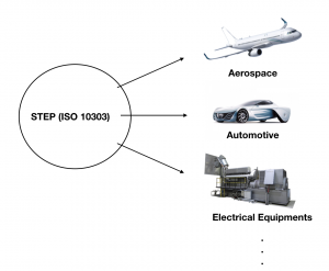
In the following years, the capabilities of STEP were widely extended, primarily for the design of products in the aerospace, automotive, electrical, electronic, and other industries

STEP CAD Format industries

The STEP format is maybe THE format of reference for CAE simulation as it is a standard in itself for the industry

I won’t detail here the structure of the file because it is much more complex than a simple text file…

In fact you would need to learn several languages of programmatic to understand how it works

(The EXPRESS language used to generate STEP files is based on other languages such as Pascal, ADA and C++).

I would like to enter in the real details of how it is composed, but this is far beyond a simple article and I would spend days to resume all the thinking that went into this standard.

But if you are really interest, I suggest you to read this article on wikipedia which will give you much more details.

You will also find a lot of interesting articles on the ISO 10303 on internet as it is a critical topic in many industries related to CAD and 3D modeling.

Now, if you are interested to know how the CAD format can actually influence your CAE simulation, I have wrote more about it in the following article.

Read my article about CAD formats and CAE Simulation:

cad-formats-article-thumbnail

CAD formats: Which one is the best for CAE?

« Back to Glossary Index

Leave a Reply Cancel reply

Your email address will not be published. Required fields are marked *

Other FEA articles:

  • What is linear static analysis in FEA simulation?What is linear static analysis in FEA simulation?
  • How to make your transducer design simulation Parametric in OnScaleHow to make your transducer design simulation Parametric in OnScale
  • How to start with Open-source FEA and Salome-Meca 2017?How to start with Open-source FEA and Salome-Meca 2017?
  • Why would you ever put your FEA in the cloud? and how?Why would you ever put your FEA in the cloud? and how?
  • 4 essential steps to solve FEA problems like a pro4 essential steps to solve FEA problems like a pro

About me

I’m an Mechanical Engineer who would like to share his passion on Finite Element Analysis to help other Engineers. Read more…

View Cyprien Rusu's profile on LinkedIn

Find videos about FEA

What is linearity and what's the difference with nonlinear simulation? - FEAforall
How to build a scientific web app in 10 min with Trame and VTK
Code Saturne Heated Square Cavity Tutorial
1/127
Next»
By PoseLab
My YouTube Channel

© Copyright since 2013 feaforall · All Rights Reserved