Today I finished my “Homework” for the NAFEMS Nonlinear Course (http://www.nafems.org/professional_development/nafems_training/training/el_nonlinear/) and I decided to write a post about this interesting exemple, the Hertz Contact !
Hertz Contact: Description of the problem
This problems describes the behavior of a steel cylinder pressed into an aluminium block. Both materials are assumed as linear elastic materials and the cylinder is loaded by a load of F= 35kN in he Vertical direction.
Analytic solution of this problem is known for 2D plain strain and frictionless model.
Results to be determined
The typical results we want to see are the peak contact stress, the contact radius and stress variation through depth under peak contact stress.
Theoretical Results
I found a nice paper giving the theoretical solution for a 2D Plane Strain Problem Here.
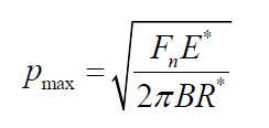
The Maximum Contact Pressure is given by:
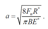
The contact Width 2a is given by:
For the given problem, the following results “should be” obtained:
Random problems that I met solving the model
1- The Force of 35kN mentioned is a point load, so if the model used is 3D and the force is applied on the top edge of the cylinder, Force is actually lineic force and the value of the force should be defined as 35kN divided by the actual thickness (Special Thank to Johan Epingga for the tip…)
2- Using symmetry boundary condition is a must as it decreases by 2 the number of elements in the model, so this is especially helpful if you run the simulation in 3D…
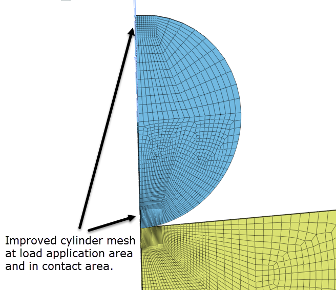
3- Mesh should be really really good in the zone of contact to get correct results, so the best is to create manually the mesh using 2D meshing and size control and then extruding all that.
4- The assignment of the load is tricky if you assign it on the nodes. Best way in this case is to link the nodes with some rigid link to one unique node on which you apply the -35/2 kN loading (symmetry–>load is divided by 2)
5- Contact parameters are also tricky, midas NFX is using the penalty method for general contact, so you should keep in mind that the penetration will play a big influence on the results. I decided to set a contact tolerance of 0.001 mm to keep the penetration acceptable.
My process to solve all that
Hypothesis
1- Theoretical solution is for 2D plain strain model, but it requires to use gap element is midas NFX, so I will solve it for a 3D Model.
2- I will general contact with penalty method and a contact tolerance of 0.01mm without friction (maybe i will try with friction too afterwards :) )
Model creation
1- Create the skeleton of the model by sketching the edges
2- Dividing edges in the right manner to apply size control
3- Meshing the 2D faces using manual map-meshing
4- Using Extrude mesh function to create 3D Mesh
Boundary conditions and loading
1- Symmetry BC is applied to the symmetric face…
2- Bottom of the block part is fixed
3- Load is applied as a point load of 17.5kN using rigid links to the nodes at the Top of the model
Contact
General contact with a contact tolerance of 0.001 mm applied to the surfaces in contact. The Master surface is the top surface of the block and the slave face is the bottom surface of the cylinder.
Results
Here is what I got for the moment :
I am not sure the results are correct…let’s find why T_T
You were right Tony, Nonlinear Analysis is not so straightforward…Hope at the end of the course I will get better results
Update (2014-11-10):
I modified a bit the model by adding soft springs and making a better contact region. I realized also that the mesh shape had a great influence on the results and I made some better mesh:
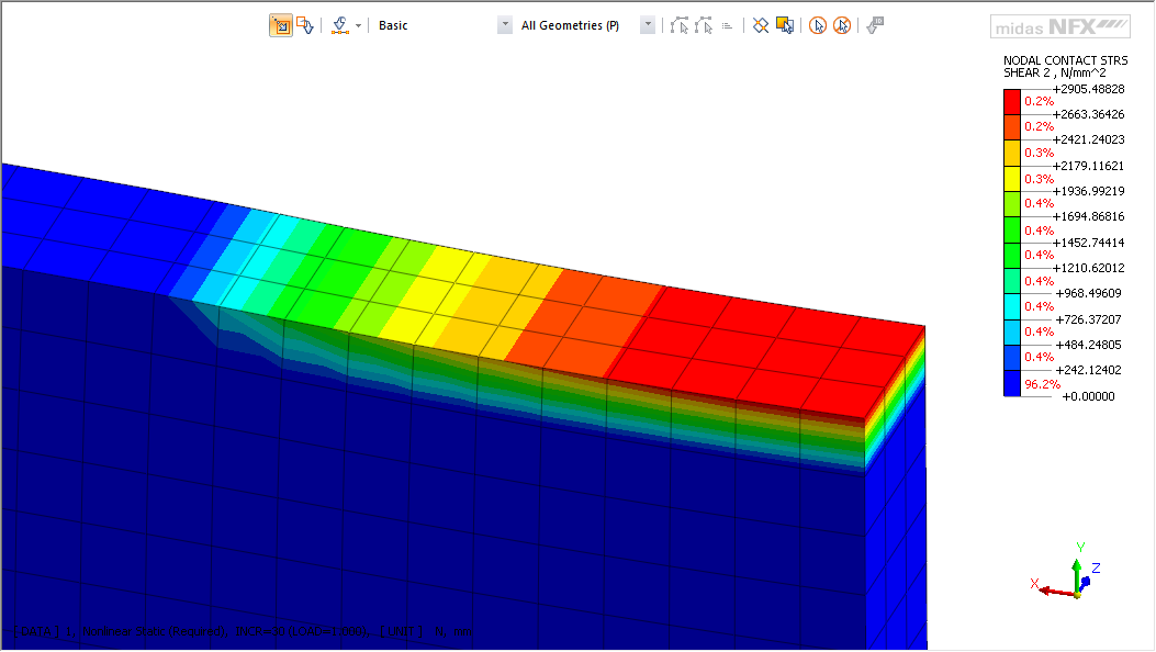
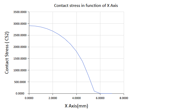
Here is the stress distribution I got in the contact area:
And here is the curve:
It proves one thing: I got much better results than in the first try with lesser elements…
Now you can see how much model building is important in FEA Nonlinear Analysis…
Thanks for following up
I invite you to add your own results in the comments and discuss about it ! :)

Cyprien, I enjoy reading your posts… and I too am blessed to be an engineer. Thanks for your efforts. Now, if I didn’t miss your mentioning this topic from your NAFEMS NL class, I recommend that you “discover” via the FEM (because you probably already know the answer empirically) the root cause and failure mechanism behind many contact stress failures, such as in gearing. Hints: 1) a linear contact solution is sufficient; 2) the solution is quite mesh-dependent; 3) case-hardening is a common solution. Keep up the good work! Regards, Keith
Thank you very much Keith ! I am glad you liked the post. is a linear contact solution really sufficient? I guess I’ll have to think more about this problem…
Cyprien, officially, this is a change of state problem, requiring iterative solution of the stiffness matrix which is by definition, a nonlinear solution. So, your suspensions are correct. However, most FEA suppliers package a multi-body contact capability with a solution for linear materials and linear displacements and call it “linear contact”. So, as long as you use linear material properties and your displacements are in the realm of a linear solution, such a capability would suffice for Hertz contact. However, given you are set up to perform a full nonlinear analysis, I would recommend you go ahead with the assumptions mentioned and numerically “discover” the root cause and failure mode of bearing contact. All the best, Keith.
I would like to know how you have plot the contact stress graph versus x axix (mm) with workbench?
it’s urgent
best regards
Check this article, Boussalia:
http://www.padtinc.com/blog/the-focus/making-charts-and-tables-in-ansys-mechanical
thanks for you cyprien
but i cant plot contact pression vs ax (mm) like you
i cant change time in axe x with the lenght of the contact area.
please show me How did you do?
hello thank for your post. can you share me the complete file
Hi Im working in a Gear Design, Where I have to find the Hertzian COntact Stress. Is it important to give the non linear behaviour to it.
Hi Harish, yes, I think for hertzian contact that you have to model it as a general contact, which is nonlinear… a linear contact is basically welded so it can only display a static contact pressure, but in case of a gear, your gear is rotating so this is definitely nonlinear…you can consider it as static though (supposing your gear rotates very slowly)
Hi
I got a problem regarding in contact stress between two cylinders(static simulation in solid works). When i run the simulation and looking at the results of contact pressure (see in vector plot), the max stress is not exactly in axial direction. the axial stress is achieved when the mesh size is above 2mm but the results are not matching with the calculations, with fine mesh at contact location can match the calculation but the axial stress is not in center exactly. Any solutions.
Hi Rahul,
Contact is never something easy to analyse… from what you describe, it seems like some contact parameters need to be changed and refined but I am not too familiar with the options you have in solidworks to do that…
Thanks but, I got results matched with my analytical solution when i did by using Abaqus.
Hi Cypren, I just reprodue the model in CalculiX, but can you upload the results file to compare both results? Best regards
Unfortunately, I haven’t those results anymore… but It’s a very good exercice, I should make a video about it with Code_Aster.
Thanks for answer! I found the original PDF benchmaks report yesterday and try to reproduce it with Salome/Prepomax/CalculiX, but still the results shows a little penetration (about 0.014mm over 0.5 of total displacement). Iwill try improving the mesh (now is free mostly hexa refined to 0.25 on the contact point).
Best regards
Hi Cyprien,
I built a model with two half-spaces in penalty contact using Abaqus/CAE. The model does NOT deform when the contact condition is enforced, BUT it deforms when the contact is deactivated. Can you help with an insight, please?
Thanks.
Hi Brian,
I’d like to help, but your description of the problem seems like you are having a problem specific to Abaqus handling of the contacts… that’s difficultly debuggable like that. I would need to have your model and all and look in depth at your contact parameters. My only advice maybe would be to check when your contact is actually recognized by the algorithm… at the start of the movement or at the end… this is linked to penalty method I guess, probably a parameter somewhere to change.
Hi Cyprien, we can not compare Hertz solution with nonlinear solution (it must be frictionless without nonlinear effects, large deflections = OFF), especially when plasticity occured. It would be very good task to create diagram in the complete loading range with deviation to the Hertz theory beyond the yield stress. In other words to simulate any hardness test. There should be plenty of experimental data on the web.
Why you selected 0.001 penetration and not 0.0001? How you verified, that 0.001 is enough?